
TB 9-6625-1996-24
b. Adjustments
NOTE
Remove top cover to make adjustments, then replace top cover
before repeating (a) above.
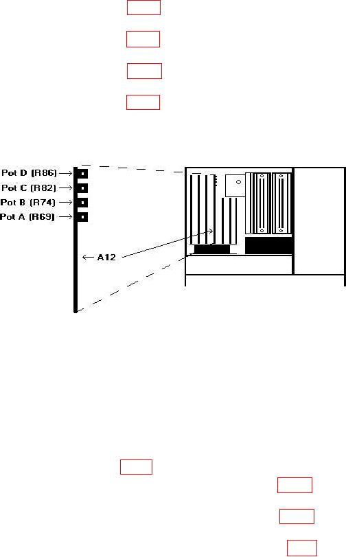
(1) Adjust A12 pot A (R69) (fig. 3) for a 2.0000 0.0005 V dc multimeter
indication (R).
(2) Adjust A12 pot B (R74) (fig. 3) for a 2.0000 0.0005 V dc multimeter
indication (R).
(3) Adjust A12 pot D (R86) (fig. 3) for a 2.0000 0.0005 V dc multimeter
indication (R).
(4) Adjust A12 pot C (R82) (fig. 3) for a +2.0000 0.0005 V dc multimeter
indication (R).
Figure 3. I/O adjustment location.
11. Power Supply
NOTE
Do not perform power supply check if all other parameters are
within tolerance.
a. Performance Check
(1) Mount circuit board A6 (fig. 1) on extender boards.
(2) Connect multimeter between A6TP6 and + 5 V RET (fig. 4). If multimeter does
not indicate between 4.98 and 5.02 V dc, perform b (1) below.
(3) Connect multimeter between A6TP3 and - 5.2 V RET (fig. 4). If multimeter does
not indicate between -5.18 and -5.22 V, perform b (2) below.
(4) Replace circuit board A6 in TI and mount circuit board A7 (fig. 1) on extender boards.