
TB 9-6625-1996-24
CHANNEL A and B SLOPE switches to + (positive).
(6)
CHANNEL A and B input impedance switches to 50 Ω.
(7)
CHANNEL A and B ATTEN switches to X1.
(8)
CHANNEL A and B AC-DC switches to DC.
(9)
CHECK-COM A-SEP switch to SEP.
(10)
8. Time Base Stability
a. Performance Check
(1) Connect a time/frequency workstation 1 MHz output to frequency difference
meter REF INPUT.
(2) Connect TI FREQ STD OUTPUT 10 MHz (rear panel) to frequency difference
meter SIG INPUT.
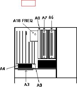
(3) Adjust A18 FREQ ADJ (fig. 1) for minimum difference indication on frequency
difference meter.
Figure 1. Test instrument - top view.
(4) Allow at least 24 hours for stabilization. Frequency difference meter indication
will remain within 5 parts in 10-10.
(5) Adjust autotransformer output to 105 V and allow 15 minutes for stabilization.
(6) Adjust autotransformer output to 125 V and allow 15 minutes for stabilization.
(7) Adjust autotransformer output to 115 V.
b. Adjustments. No further adjustments can be made.