
TB 9-6625-2011-35
(2) Position controls as listed in (a) and (b) below.
(a) PULSE PERIOD(S) switch to 1-.1m and VERNIER control fully cw.
(b) PULSE WIDTH(S) switch to 1-.1m and VERNIER control to center.
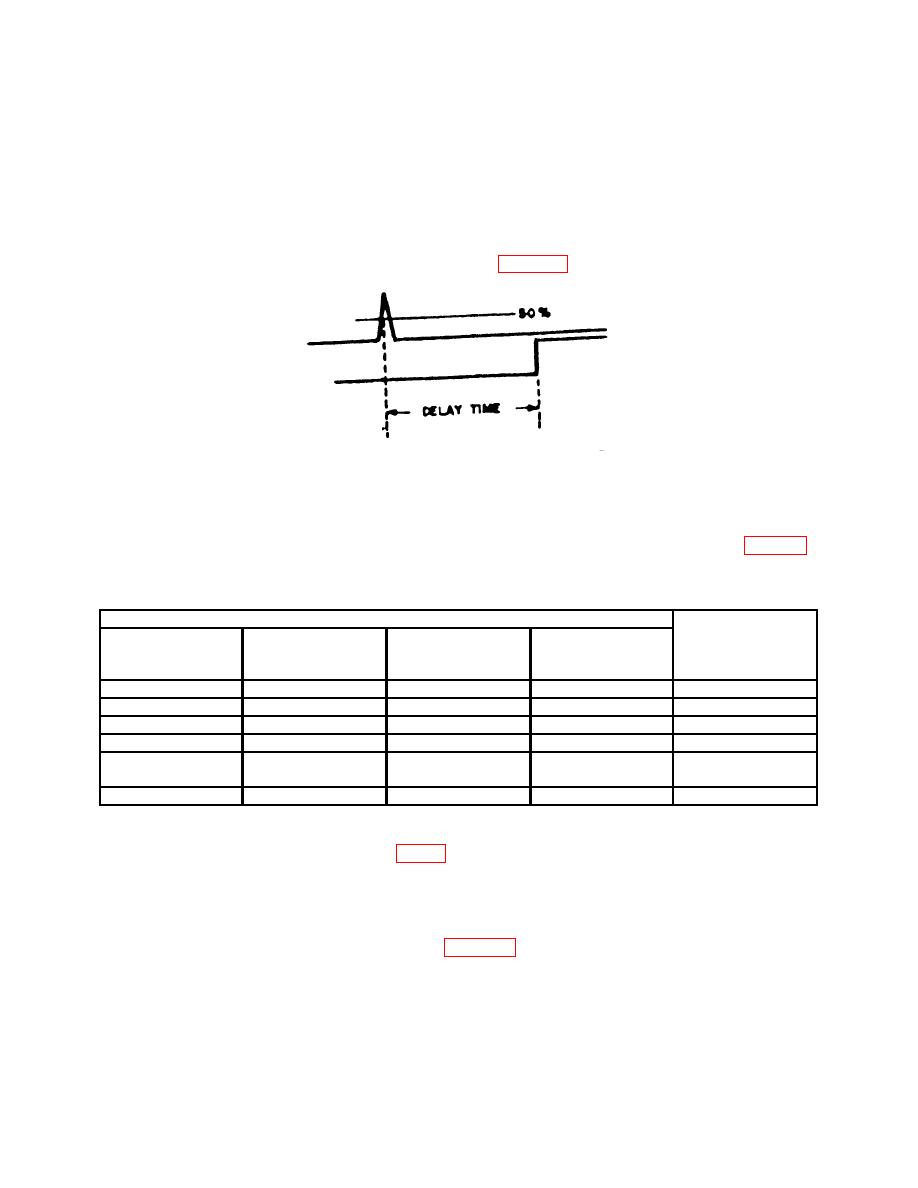
(3) Adjust PULSE DELAY VERNIER control fully ccw. Measure delay between
trigger output and pulse at 50 percent amplitude as indicated on oscilloscope. Pulse
delay will be less than 35 ns, similar to display on figure 3.
(4) Adjust PULSE DELAY VERNIER control fully cw. If delay, as indicated on
oscilloscope, is not between 1.1 and 1.35 s, perform b below.
(5) Repeat technique of (2) through (4) above, using TI settings listed in table 4.
Pulse delay will be within limits specified.
Test instrument
PULSE
PULSE
PULSE
PULSE DELAY
DELAY(S)
PERIOD(S)
WIDTH(S)
VERNIER
Oscilloscope
switch settings
switch settings
switch settings
control position
indications
1 - . 1m
1 - .1m
s
. 1m - 10m
cw
>100
1 - . 1m
1 - .1m
s
. 1m - 10m
ccw
<1
. 1m - 10m
10m-1
. 1m - 10m
cw
>10
ms
1
s
. 1m - 10m
. 1m - 10m
. 1m - 10m
ccw
<100
10m - 1
(+) EXT
.1 - 10m
cw
>1
s
(Press MAN)
10m - 1
10m - 1
.1m - 10m
ccw
<10
ms
1Adjust
PULSE PERIOD VERNIER control to midposition. Return to cw position after this check.
10. Pulse Width
a. Performance Check
(1) Connect equipment as shown on figure 2.
(2) Position controls as listed in (a) through (c) below:
