
TB 9-6625-2023-35
(d) MATH OFF key to on.
(e) AUTO CAL key to on.
(f) GUARD pushbutton pressed to on.
(g) AC-AC/DC switch (rear panel) to AC.
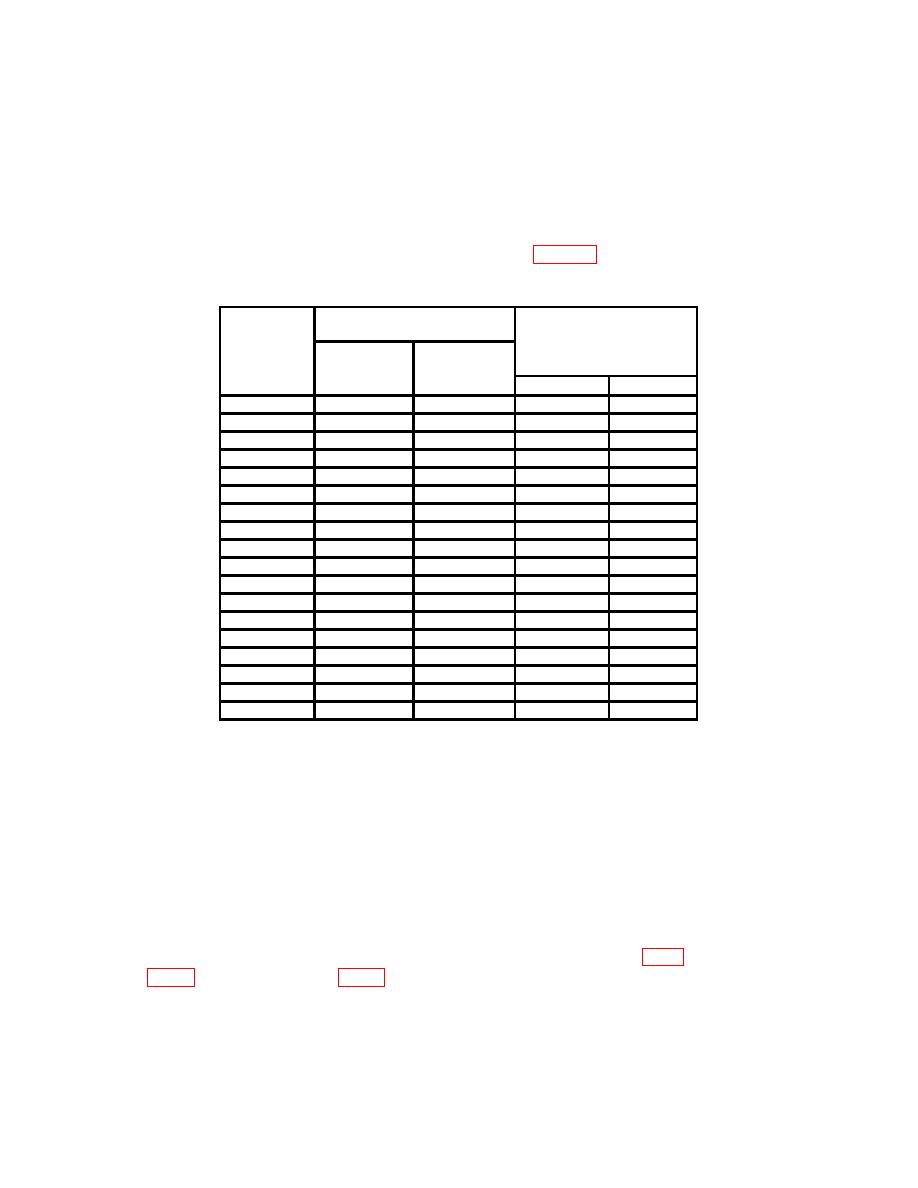
(3) Set TI and calibrator to settings listed in table 6. If TI indications are not
within limits specified, perform b below.
Table 6. Ac Voltage
Calibrator
Test
output settings
instrument
Test instrument
RANGE
indications
Voltage
settings
(V)
(Hz)
Min
Max
1
1
30
0.9988
1.0012
1
1
100
0.9988
1.0012
1
1
40 k
0.9927
1.0073
1
1
200 k
0.976
1.024
1
1
400 k
0.943
1.057
1
1
1M
0.902
1.098
10
10
30
9.988
10.012
10
10
100
9.988
10.012
10
10
40 k
9.927
10.073
10
10
200 k
9.76
10.24
10
10
400 k
9.43
10.57
10
10
1M
9.02
10.98
100
100
30
99.88
100.12
100
100
100
99.88
100.12
100
100
40 k
99.27
100.73
100
100
100 k
99.27
100.73
1000
1000
40
997
1003
1000
1000
10 k
997
1003
b. Adjustments
NOTE
Adjustments are labeled on top inner cover. Top inner cover
must be removed to gain access to test points on circuit
boards.
(1) Set calibrator to STANDBY and disconnect from TI.
(2) Press TI RANGE 10 key to on.
(3) Short INPUT (2 WIRE) HI and LO using copper wire or shorting bar.
(4) Connect multimeter (V dc mode) INPUT HI to A15 TP8 (fig.1) and LO to A15
10
