
TB 9-6625-2059-24
(12) Reduce signal generator amplitude until FREQ ERROR meter indicates a
100 Hz error from indication recorded in (11) above.
(13) If signal generator amplitude is greater than -101 dBm perform b (6) through
(11) below.
b. Adjustments
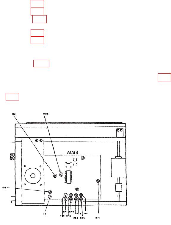
(1) Adjust A1A13R44 (fig. 5) for an oscilloscope indication of -10 kHz.
(2) Adjust A1A13R39 (fig. 5) until FREQ ERROR meter indicates 10 kHz.
(3) Adjust A1A13R44 (fig. 5) for best in-tolerance condition while repeating a (1)
through (7) above.
(4) Adjust A1A13R41 (fig. 5) until FREQ ERROR meter indicates 4 kHz.
(5) Adjust A1A13R42 (fig. 5) until FREQ ERROR meter indicates 1 kHz.
(6) Adjust signal generator amplitude for -107 dBm.
(7) Set RCVR WIDE-MID-NARROW switch to WIDE.
(8) Adjust A1A13R7 (fig. 5) until INPUT LEVEL lamp (front panel) just
illuminates.
(9) Set RCVR WIDE-MID-NARROW switch to NARROW. Adjust A1A13R8 (fig. 5)
until INPUT LEVEL lamp just illuminates.
(10) Set DEV-PWR switch to SIG. Adjust signal generator amplitude to -25 dBm.
Adjust A1A13R91 (fig. 5) until DEVIATION/WATTS meter indicates FS.
(11) Repeat (6) through (10) above as necessary.
Figure 5. Test Instrument - Right View.
17