
TB 9-6625-2059-24
(14) Adjust signal generator amplitude for -90 dBm.
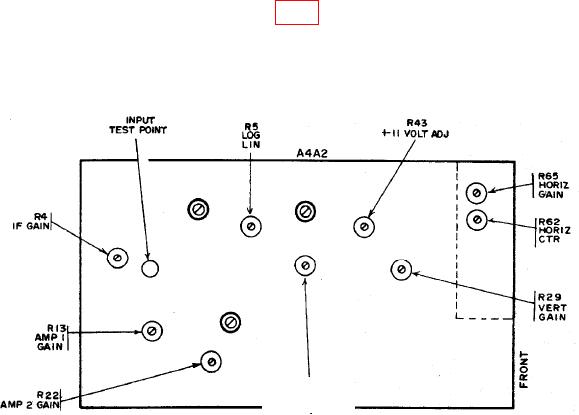
(15) Adjust AMP 2 GAIN A4A2R22 (fig. 6) for a -90-dBm indication on TI.
(16) Repeat b (12) through (15) above until no further adjustments are required.
(17) Adjust signal generator amplitude for -30 dBm and repeat b (7) through (16)
above until no further adjustments are required.
R30
VERT CTR
Figure 6. Spectrum Analyzer No. 2 - Adjustment Locations.
17. Spectrum Analyzer Centering and Bandwidth
a. Performance Check
(1) Adjust signal generator frequency for 125.500 MHz and amplitude for -50 dBm.
If peak of signal strength is not aligned with center vertical graticule line 2 minor
divisions and end of trace is not aligned with right edge of bezel (5.4 divisions from center),
perform b (1) through (3) below.
(2) Adjust ANALY DISPR control fully cw. If peak of signal strength is not aligned
with center vertical graticule line within 2 minor divisions, perform b (1) below.
(3) Set FREQUENCY MHz switches to indicate 130 500 0. If signal strength peak
is not aligned with first vertical graticule line within 2 minor divisions, perform b (4)
below.
(4) Decrease FREQUENCY MHz switches from 130 500 0 to 120 500 0 in
increments of 001 000 0. If signal strength does not move 1 major division per increment
within 2 minor divisions, perform b (5) through (7) below.
(5) Adjust ANALY DISPR control fully ccw but not to detent.
(6) Set FREQUENCY MHz switches to 126 000 0. If signal strength peak is not
aligned with first vertical graticule line 2 minor divisions, perform b (8) below.