
TB 9-6625-2069-24
(6) Measure delay between leading edge of first pulse and leading edge of second
pulse, using standard measurement technique. Delay, as indicated on oscilloscope, will be
between 18.8 and 21.2 ns.
(7) Press DBL PLS pushbutton and enter data of 80 ns.
(8) Repeat (6) above. Delay, as indicated on oscilloscope, will be between 78.2 and 81.8 ns.
(9) Disconnect equipment setup.
(10) Connect OUTPUT A to frequency counter input B and connect TRIG OUTPUT
to frequency counter input A.
(11) Set frequency counter for TIME A-B measuring function.
(12) Press TI pushbuttons and enter data as listed in (a) and (b) below:
(a) PERIOD to 10 s.
(b) DELAY to 500 ns.
(13) Press frequency counter MEASUREMENT RESTART key. Frequency counter
will indicate between 494 and 506 ns.
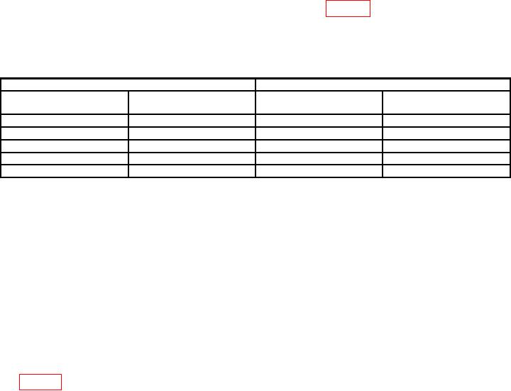
(14) Press pushbuttons and enter data as listed in table 7. Frequency counter will
indicate within limits specified.
(15) Repeat (1) through (14) above for OUTPUT B (option 020).
Table 7. Delay - High Range
Test instrument
Frequency counter indications
PERIOD
DELAY
data
data
Min
Max
s
s
100
1.00
989
ns
1011
ns
s
s
s
1.00
ms
50.0
49.499
50.501
s
s
500
ms
1.00
ms
990
1010
999
ms
500
ms
495
ms
505
ms
999
ms
900
ms
891
ms
909
ms
b. Adjustments. No adjustments can be made.
10. Width Accuracy
a. Performance Check
(1) Connect OUTPUT A to input A of frequency counter and set frequency counter
for P WIDTH A measuring function. Set frequency counter for 50 impedance.
(2) Set DELAY switch to 0 ns (both channels for option 020).
(3) Set TI PERIOD data to 200 ns and WIDTH data to 10 ns.
(4) Press frequency counter MEASUREMENT RESTART key.
Pulse width as
measured by frequency counter will be between 8.9 and 11.1 ns.
(5) Repeat technique of (3) and (4) above, using PERIOD and WIDTH data listed
in table 8. Pulse width will be within limits specified.