
TB 9-6625-2069-24
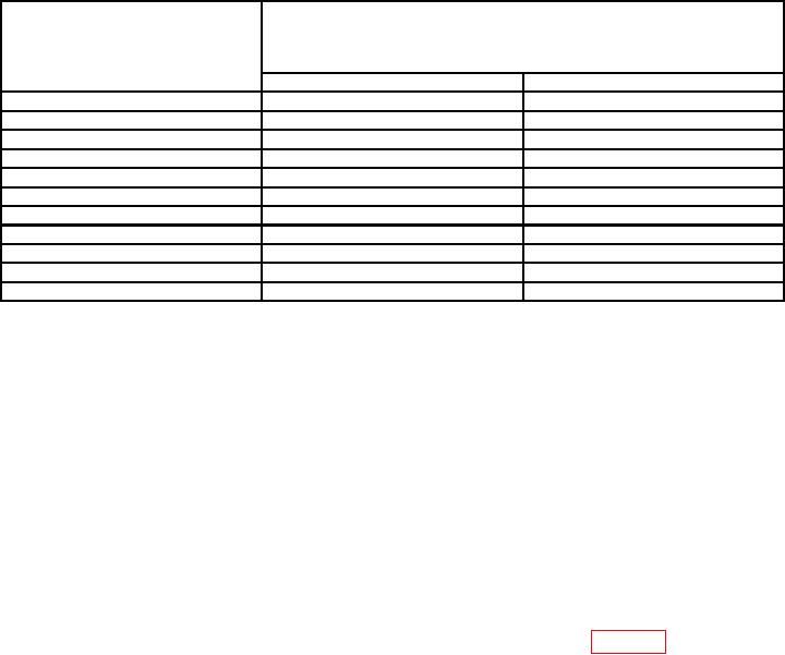
Table 10. Output Level Accuracy
Test instrument
HIL data
(V)
indications (dc)
or LOL data
(-V)
Min
Max
0.491
mV1
mV1
430
550
0.99
920
mV
1060
mV
1.99
1.900
V
2.08
V
2.99
2.88
V
3.10
V
3.99
3.86
V
4.12
V
7.99
7.78
V
8.20
V
9.99
9.74
V
10.24
V
10 2
9.70
V
10.30
V
13
12.64
V
13.36
V
17
16.56
V
17.44
V
19.9
19.40
V
20.40
V
1When
checking LOL data, all voltage indications will be negative.
checking CHANNEL A, press 1k /50 pushbutton to 1k and CHANNEL B 1k /50
pushbutton to 50 .
2When
When checking CHANNEL B, press 1k /50 pushbutton to 1k and CHANNEL A 1k /50
pushbutton to 50 .
NOTE
When checking HIL voltage, leave LOL at 0.0 V.
(5) Press pushbuttons and enter data as listed in (a) through (d) below (both
channels for option 020).
, NORM.
CHANNEL A for 50
(a)
, NORM.
CHANNEL B for 50
(b)
LOL to - 0.10 V.
(c)
HIL to 0 V.
(d)
(6) Multimeter will indicate between -48 and -152 mV.
(7) Repeat technique of (5) and (6) above using data listed in table 11. Multimeter
will indicate within limits specified.
NOTE
When checking LOL voltage leave HIL at 0.0 V.
(8) Press CHANNEL A and CHANNEL B 1k /50
pushbuttons to 50
.
(9) Press LOL pushbutton to -.1 V.
(10) Repeat (1) through (9) above for OUTPUT B (option 020 only).
b. Adjustments. No adjustments can be made.
12