
TB 9-6625-2097-24
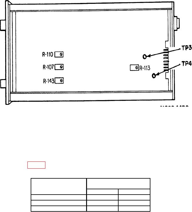
Figure 4. Model 13-4618-00 - side view.
(7) A d j u s t c a l i b r a t o r f r e q u e n c y f o r 6 0 H z . I f m u l t i m e t e r d o e s n o t i n d i c a t e
0 100 mV, perform b (3) below.
(8) Zero the multimeter.
(9) Adjust calibrator frequency for 59 Hz. If the multimeter does not indicate
between -4.975 and -5.025 V, perform b (4) through (7) below.
(10) Repeat technique of (7) through (9) above for DEVIATION RANGE switch
positions listed in table 4. Multimeter indicator differences will be within limits specified.
Table 4. Span Gain Accuracy
Test instrument
Multimeter indications
DEVIATION RANGE
(V)
switch settings
Min
Max
1
-2.4875
-2.5125
2.5
-0.9950
-1.0050
5
-0.4975
-0.5025
(11) Set DEVIATION RANGE switch to blue range.
(12) Set TI CENTER FREQUENCY switch to 400.
(13) Adjust calibrator frequency for 400 Hz. Multimeter should indicate 0 100 mV.
(14) Zero the multimeter.
(15) Adjust calibrator frequency for 390 Hz. Multimeter should indicate between
-4.9700 and -5.0300 V.
11