
TB 9-6625-2114-35
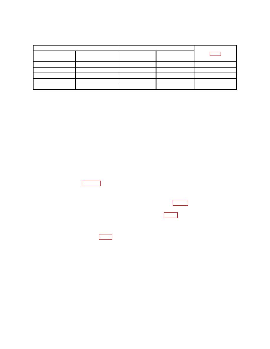
Test instrument
Calibrator indications (V ac)
Adjustments
RANGE
switch settings
Indications
Min
Max
(R)
RX10 3V
3
2.910
3.090
R39
3 VAC
RX100 10V
11
9.70
10.30
R40 10 VAC
RX1K 30V
3
29.10
30.90
R36 30 VAC
RX10K 100V
1
97.0
103.0
R37 100 VAC
RX100K 300V
3
291.0
309.0
R38 300 VAC
1After
this check, and only if capacitive voltage divider is supplied with TI, set calibrator for a 9 V, 10 kHz output.
Record
TI indication for use in (9) below. Set calibrator frequency to 400 Hz for remaining ranges.
NOTE
Perform (6) through (9) below only if capacitive voltage
divider is supplied with TI.
(6) Set RANGE switch to R100 10V.
(7) Connect capacitive voltage divider to AC PROBE. Connect capacitive
voltage divider tip and ground clip lead together and adjust AC ZERO for 0 meter
indication.
(8) Connect capacitive voltage divider and ground clip lead to calibrator
OUTPUT HI and LO.
(9) Set calibrator for a 900 V, 10 kHz output. Adjust calibrator amplitude for TI
indication recorded in table 4. Calibrator will indicate between 891.0 and 909.0 V.
b. Adjustments
(1) Connect multimeter INPUT HI t o V6 PIN 7 (fig. 1) and LO ground. If
multimeter does not indicate between 4.9 and 5.1 V ac (for AC PROBE diode 2-01C) or
6.2 and 6.4 V ac (for AC PROBE diode EA53), adjust R50 (fig. 1) for 5 V ac or 6.3 V ac as
applicable (R).
(2) Set calibrator to 1.000 V.
(3) Adjust R35 1 VAC (fig. 1) for a 1 V indication on TI (R).
10. Frequency Response
a. Performance Check
(1) Set RANGE switch to RX1 1V.
(2) Connect AC PROBE tip and ground clip lead together and adjust AC ZERO
for 0 indication on TI.
(3) Connect TI AC PROBE tip and ground clip lead to calibrator OUTPUT HI
and LO.
