
TB 9-6625-2117-24
8. Vertical Gain
a. Performance Check
(1) Connect oscilloscope calibrator SOURCE/MEASURE CHAN 1 and CHAN 2 to
TI CH 1 and CH 2 inputs respectively.
(2) Set oscilloscope calibrator for a CHAN 1, VOLTAGE mode output of 5 mV at
1 kHz frequency.
(3) Rotate oscilloscope calibrator knob below EDIT FIELD pushbutton to adjust
amplitude for 5 divisions of deflection on TI. If oscilloscope calibrator err display does not
indicate within limits specified in first row of table 3, perform b (1) and (2) below.
(4) Repeat technique of (2) and (3) above for settings listed in table 3. Oscilloscope
calibrator err display will indicate within limits specified in table 3.
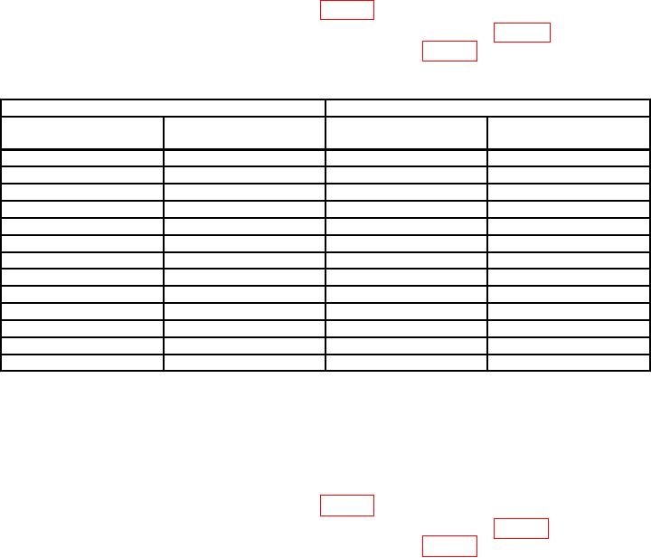
Table 3. Vertical Gain Check CH 1
Test instrument
Oscilloscope calibrator
CHAN 1 VOLTAGE
Err display
VOLTS/DIV
Vertical deflection
output
limits (%)
switch settings
(divisions)
1 mV
5 mV
3
5
2 mV
10 mV
3
5
5 mV
20 mV
3
4
10 mV
50 mV
3
5
20 mV
0.1 V
3
5
50 mV
0.2 V
3
4
0.1 V
0.5 V
3
5
0.2 V
1.0 V
3
5
0.5 V
2.0 V
3
4
1 V
5.0 V
3
5
2 V
10.0 V
3
5
5 V
20.0 V
3
4
10 V
40.0 V
3
5
(5) Press vertical mode CH 2 and TRIGGER SOURCE COMP pushbuttons.
(6) Set oscilloscope calibrator for a CHAN 2, VOLTAGE mode output of 5 mV at
1 kHz frequency.
(7) Rotate oscilloscope calibrator knob below EDIT FIELD pushbutton to adjust
amplitude for 5 divisions of deflection on TI. If oscilloscope calibrator err display does not
indicate within limits specified in first row of table 4, perform b (3) and (4) below.
(8) Repeat technique of (6) and (7) above for settings listed in table 4. Oscilloscope
calibrator err display will indicate within limits specified in table 4.