
TB 9-6625-2117-24
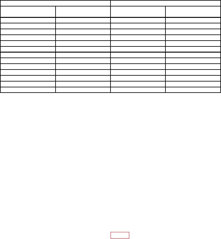
Table 4. Vertical Gain Check CH 2
Test instrument
Oscilloscope calibrator
CHAN 1 VOLTAGE
err display
VOLTS/DIV
Vertical deflection
output
limits (%)
switch settings
(divisions)
1 mV
5 mV
3
5
2 mV
10 mV
3
5
5 mV
20 mV
3
4
10 mV
50 mV
3
5
20 mV
0.1 V
3
5
50 mV
0.2 V
3
4
0.1 V
0.5 V
3
5
0.2 V
1.0 V
3
5
0.5 V
2.0 V
3
4
1 V
5.0 V
3
5
2 V
10.0 V
3
5
5 V
20.0 V
3
4
10 V
40.0 V
3
5
(9) Reduce outputs to minimum and disconnect equipment setup.
b. Adjustments
(1) Adjust oscilloscope calibrator variable control for 0 indication on err readout.
(2) Adjust CH 1 GAIN (front panel) for 5 divisions of vertical deflection.
(3) Adjust oscilloscope calibrator variable control for 0 indication on err readout.
(4) Adjust CH 2 GAIN (front panel) for 5 divisions of vertical deflection.
9. CH 1 and CH 2 Volts/Div Compensation
a. Performance Check
(1) Connect oscilloscope calibrator SOURCE/MEASURE CHAN 1 to TI CH 1
input, using a 50 feedthrough termination and a 5-80 pF standardizer.
(2) Set CH 1 and CH 2 VOLTS/DIV switches to 10 mV.
(3) Press vertical mode CH 1 and TRIGGER SOURCE CH 1 pushbuttons.
(4) Set oscilloscope calibrator for a CHAN 1, EDGE mode output of 1 kHz and
adjust amplitude for 5 divisions of vertical deflection.
(5) Adjust standardizer for optimum square corner and flat top. If standardizer
cannot be adjusted for optimum square wave, perform b below.
(6) Adjust oscilloscope calibrator amplitude for 5 divisions of vertical deflection at
each TI VOLTS/DIV switch settings listed in table 5. If TI does not display square corners
and flat tops, perform b below.