
TB 9-6625-2117-35
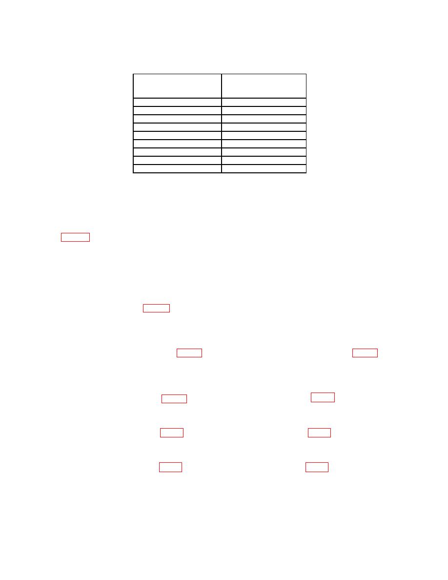
Test instrument
Oscilloscope calibrator
VOLTS/DIV switch
amplitude output
setting
(divisions)
5 mV
5
2 mV
5
1 mV
5
20 mV
5
50 mV
5
.1 V
5
.5 V
5
1 V
5
2 V
5
(7) Press vertical mode CH 2 and TRIGGER SOURCE COMP pushbuttons.
(8) Set oscilloscope calibrator for a CHAN 1, EDGE mode output of 1 kHz and
adjust amplitude for 5 divisions of vertical deflection.
(9) Repeat technique of (5) and (6) above for TI VOLTS/DIV switch settings listed
in table 5 for CH 2. If TI does not display square corners and flat tops, perform b below.
b. Adjustments.
(1) Set CH 1 VOLTS/DIV switch to 10 mV and press vertical mode CH 1 and
TRIGGER SOURCE CH 1 pushbuttons.
(2) Set oscilloscope calibrator for a CHAN 1, EDGE mode output of 1 kHz and
adjust amplitude for 5 divisions of vertical deflection.
(3) Adjust C9 (fig. 1) to midrange and readjust standardizer for optimum
square wave.
(4) Set TI CH 1 VOLTS/DIV switches to 20 mV and adjust oscilloscope calibrator
output amplitude for 5 divisions of vertical deflection.
flat top (R).
(6) Set TI CH 1 VOLTS/DIV switches to 50 mV and adjust oscilloscope calibrator
output amplitude for 5 divisions of vertical deflection.
(8) Set TI CH 1 VOLTS/DIV switches to .1 V and adjust oscilloscope calibrator
output amplitude for 5 divisions of vertical deflection.
(10) Set TI CH 1 VOLTS/DIV switches to 1 V and adjust oscilloscope calibrator
output amplitude for 5 divisions of vertical deflection.
(12) Set CH 2 VOLTS/DIV switch to 10 mV and press vertical mode CH 1 and
TRIGGER SOURCE CH 1 pushbuttons.
7
