TB 9-6625-2117-35
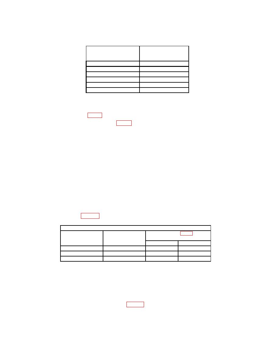
Table 6. Sweep Calibration - Continued
Test instrument
Oscilloscope calibrator
TIME/DIV
MARKER
switch settings
outputs
.1
s
.1
s
.2
s
.2
s
.5
s
.5
s
1
s
1
s
2
s
2
s
5
s
5
s
b. Adjustments
(1) Adjust C716 (fig. 2) for 1 marker per divisions (R).
(2) Adjust C871 and C881 (fig. 2) for best compromise excluding first and last 2
divisions of magnified sweep (R).
a. Performance Check
(1) Position controls as listed in (a) and (b) below:
(a) CH 1 and CH 2 VOLTS/DIV switches to 10 mV.
(b) Push and turn TIME/DIV MAG switch to .02 s.
(2) Set oscilloscope calibrator for a CHAN 1, EDGE mode output of 100 kHz and
adjust amplitude for 6 divisions of vertical deflection.
(3) Measure risetime, using standard risetime technique. If measured risetime is
not ≥ 14 ns and aberrations are not less than 2 minor divisions, perform b (1) through (5)
below.
(4) Repeat technique of (2) and (3) above, for TI VOLTS/DIV switch settings and
adjustments listed in table 7 (R).
Test instrument
VOLTS/DIV switch
Measured risetime
Adjustments (fig. 1) (R)
settings
limits
(mV)
(ns)
CH 1
CH 2
≥ 15.2
5
C225
C325
2
C223
C323
≥ 17.5
1
C220
C320
≥ 19.5
(5) Press TI VERTICAL MODE CH 2 and TRIGGER SOURCE COMP
pushbuttons.
(6) Set oscilloscope calibrator for a CHAN 2, EDGE mode output of 100 kHz and
adjust amplitude for 6 divisions of vertical deflection
(7) Repeat technique of (3) above, using TI CH 2 controls. If measured risetime is
not within limits specified in first row of table 7, perform b (6) below.
(8) Repeat technique of (3) and (4) above for CH 2.


