
TB 9-6625-2132-24
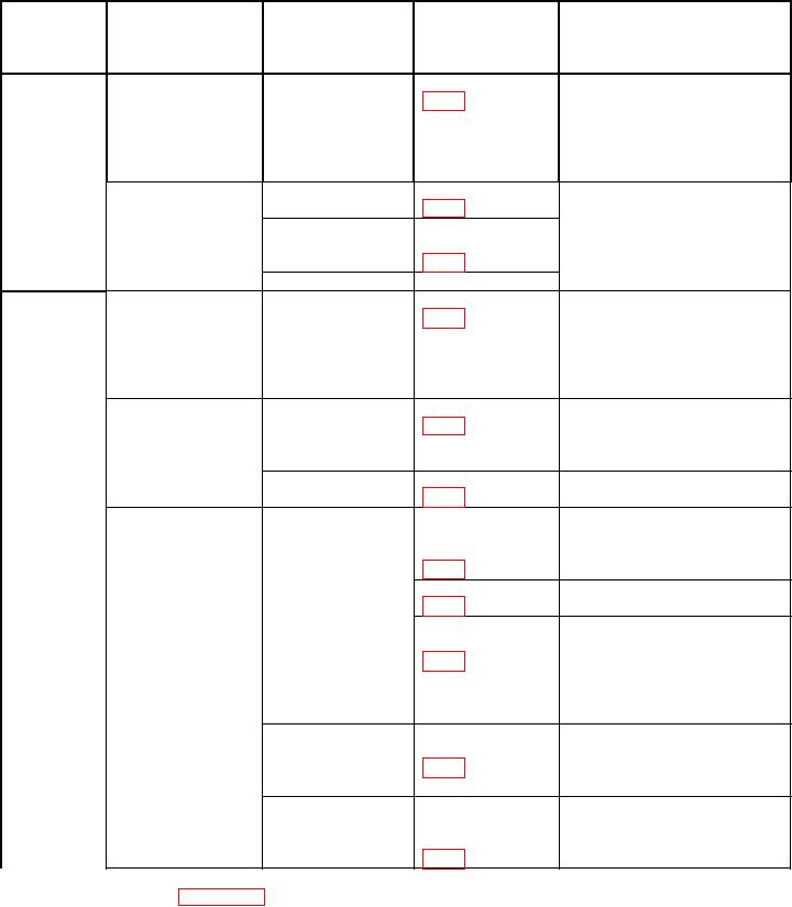
Table 6. High-Frequency Compensation and Adjustment Sequence
Test
calibrator
Time base sweep
Adjustments
Procedures
instrument
EDGE frequency
rate
SN range
setting
R196 (R)1
B040000
10 kHz
.1 ms/div
Set TI VOLTS/DIV switch to
and above
10 mV and press BW push-
button to 5 MHz. Adjust for
best flat top. Press BW
pushbutton to FULL for
remaining adjustments.
.5 s/div
100 kHz
Adjust for optimum square
R432 (R)
corner.
.5 s/div
R336 (R)
or 1 s
R432 (R)
50 ns/div
R333 (R)
20 s/div
R196 (R)2 3
B039999
10 kHz
Set TI VOLTS/DIV switch to
and below
10 mV and press BW push-
button to 5 MHz. Adjust for
best flat top. Press BW
pushbutton to FULL for
remaining adjustments.
1 s/div
R432 (R)
Adjust for optimum square
100 kHz
corner. (Ignore fast
spike if any, that may
remain on top front corner.)
.1 s/div
R300 (R)
Adjust for best flat top.
100 kHz
5 or 10
C187 (R)
Adjust for optimum square
ns/div
R187 (R)
corner.
C163 (R)
C113 (R)
Adjust for minimum ripple
near front corner.
C150 (R)
Adjust for optimum square
C250 (R)
corner. Adjust in equal
increments to maintain
C150 and C250 at/or near
the same physical
positions.
4
10 ns/div
C213 (R)
Press - polarity pushbutton.
Adjust for optimum square
C250 (R)
corner on bottom portion of
Press + polarity pushbutton.
5 ns/div
C150 (R)
Readjust for optimum
C113 (R)
square corner.
C163 (R)
1If
R196 is adjusted, repeat 11 a (4).
2If
R196 is adjusted, repeat paragraph 11 a (5).
3Press +INPUT pushbutton to GND and -INPUT pushbutton to DC. Set time base trigger slope switch to - (negative).
4Press +INPUT pushbutton to DC, -INPUT pushbutton to GND, VOLTS/DIV switch to 10 mV, and BW pushbutton to 5 MHz.
Press time base trigger slope pushbutton to +, MAGNIFIER pushbutton to X1, and TIME/DIV switch to 50 s. Adjust
oscilloscope calibrator to 10 kHz and amplitude for 8 divisions of vertical deflection on oscilloscope.
10