
TB 9-6625-2132-24
16. Attenuation Compensation
a. Performance Check
(1) Connect oscilloscope calibrator SOURCE/MEASURE CHAN 1 output to TI
+INPUT, using termination.
(2) Set VOLTS/DIV switch to 50 mV and POSITION control to midrange.
(3) Press oscilloscope calibrator EDGE key and set oscilloscope calibrator output for
1 kHz and 5 divisions of vertical deflection on oscilloscope. If upper leading corner is not
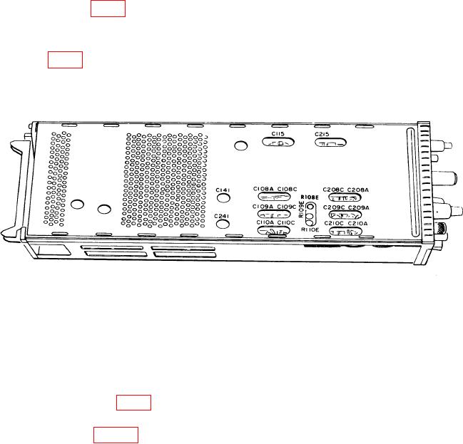
square, adjust C241 (fig. 3) for optimum square wave (R).
(4) Remove connection from +INPUT and connect to -INPUT.
(5) Press -AC-GND-DC pushbutton to DC. If lower leading corner is not square,
adjust C141 (fig. 3) for optimum square wave (R).
(6) Set VOLTS/DIV switch to .1 V.
(7) Press +AC-GND-DC pushbutton to DC and -AC-GND-DC pushbutton to GND.
Figure 3. Adjustment locations - left side view (Type 7A22).
(8) Connect oscilloscope calibrator SOURCE/MEASURE CHAN 1 output to TI
+INPUT, using standardizer.
(9) Press oscilloscope calibrator VOLTAGE key and set oscilloscope calibrator
output for 1 kHz and 6 divisions of vertical deflection on oscilloscope. Center displayed
pulse vertically on crt.
(10) Adjust standardizer for optimum square wave. If optimum square wave cannot
be obtained, adjust C115 (fig. 3) for optimum square wave (R).
(11) Repeat technique of (10) above for TI VOLTS/DIV switch settings and
adjustments listed in table 8.
b. Adjustments. No further adjustments can be made.