
TB 9-6625-2132-24
Table 8. Attenuator Compensation
Test
Adjustments (fig. 3)
instrument
VOLTS/DIV
+INPUT
-INPUT
switch
Leading
Flat top
Flat bottom
settings
corner
50 mV
C108C (R)
C108A (R)
C208A (R)
20 mV
---
---
---
10 mV
---
---
C215 (R)
.1 V
---
---
---
.2 V
C109C (R)
C109A (R)
C209A (R)
.5 V
---
---
---
1 V
---
---
---
5 V
C110C (R)
C110A (R)
C210A (R)
2 V
---
---
---
10 V
---
---
---
17. Input Attenuator Differential Balance
a. Performance Check
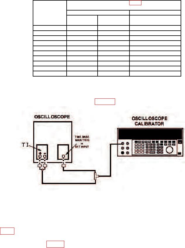
(1) Connect equipment as shown in figure 4.
Figure 4. Differential balance - equipment setup (Type 7A22).
(2) Set VOLTS/DIV switch to 50 mV and press + and -AC-GND-DC pushbuttons to DC.
(3) Set oscilloscope time base TRIGGER SOURCE switch to EXT.
(4) Press oscilloscope calibrator VOLTAGE key and set oscilloscope calibrator for a
50 V, 1 kHz output. If display on oscilloscope is not of minimum amplitude, adjust R108E
(fig. 3) for minimum amplitude (R).
(5) Repeat technique of (4) above for TI VOLTS/DIV switch settings and
adjustments listed in table 9.
b. Adjustments. No further adjustments can be made.