
TB 9-6625-2142-40
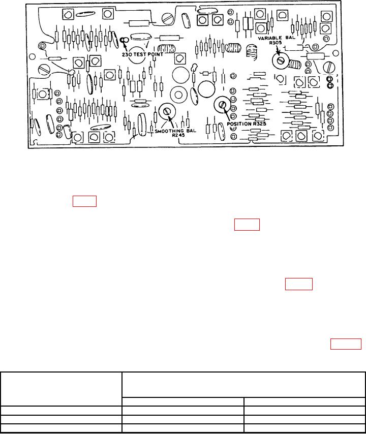
Figure 2. Sampling unit - right side view.
(7) Adjust DC OFFSET and FINE controls for 0 V dc indication on multimeter. If
trace on crt display is not aligned with the center horizontal graticule line, adjust
POSITION R325 (fig. 2) for proper indication.
(8) Press SMOOTH pushbutton. If trace on crt display is not aligned with center
horizontal graticule line, adjust SMOOTHING BAL R245 (fig. 2) for minimum trace shift
while alternately pushing SMOOTH and NORMAL pushbuttons.
(9) Press NORMAL pushbutton.
(10) Release VARIABLE (CAL IN) control to out position.
(11) Adjust VARIABLE (CAL IN) control fully cw and ccw. If trace on crt display
shifts more than 1 minor division, adjust VARIABLE BAL R305 (fig. 2) for proper
indications.
(12) Press VARIABLE (CAL IN) control to in position.
(13) Adjust DC OFFSET and FINE controls to position trace on crt display 2
divisions below center horizontal line. Multimeter will indicate +3.92 to +4.08 V dc.
(14) Repeat technique of (13) above for each mVOLTS/DIV switch setting in table 3.
Multimeter indications will be within limits specified.
Table 3. Vertical Deflection mVOLTS/DIV Accuracy
Multimeter indications
Test instrument
(V Dc)
mVOLTS/DIV
switch settings
Min
Max
100
+1.96
+2.04
50
+0.98
+1.02
20
+0.392
+0.408
(15) Disconnect multimeter. Set mVOLTS/DIV switch to 200.
7