
TB 9-6625-2155-24
(4) Set measuring receiver for an FM measurement and 300 Hz HP FILTER, 3
kHz LP FILTER, and +PEAK detector.
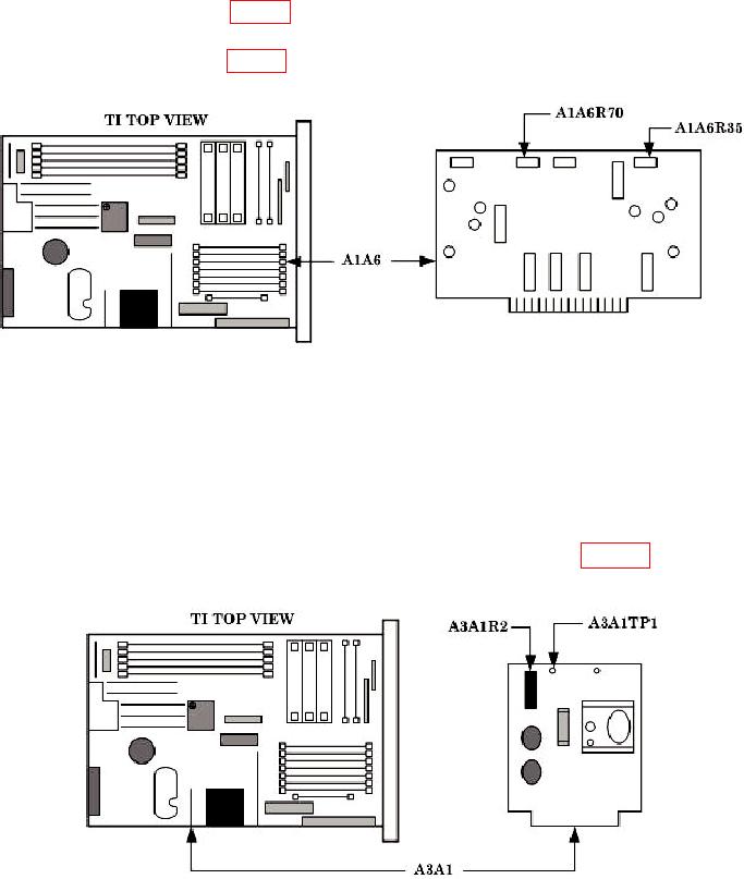
(5) Adjust A1A6R35 (fig. 11) for an indication of 100.0 1 kHz FM deviation on the
measuring receiver (R).
(6) Adjust A1A6R70 (fig. 11) until TI meter indicates 100 kHz FM deviation (needle
at full scale) (R).
Figure 11. FM Adjustment locations.
(7) Reduce all outputs to minimum.
(8) Replace TI top cover.
15. Power Supply
a. Performance Check
(1) Connect digital multimeter to A3A1TP1 and chassis (fig. 12). If digital
multimeter does not indicate between +21.98 and +22.02 V dc, perform b (1) below.
Figure 12. A3A1 card.