
TB 9-6625-2155-24
(16) Set measuring receiver to measure the distortion of the 1 kHz AM signal.
(17) The measuring receiver will indicate within limits listed in table 17 for the
current audio analyzer source frequency and level.
(18) Set the audio analyzer to produce a 10 kHz signal at 0.425 V.
(19) Set measuring receiver to measure FM using + PEAK detector.
(20) The measuring receiver will indicate within limits listed in table 17 for the TI
frequencies and audio analyzer settings.
(21) Repeat (20) for remaining settings in table 17.
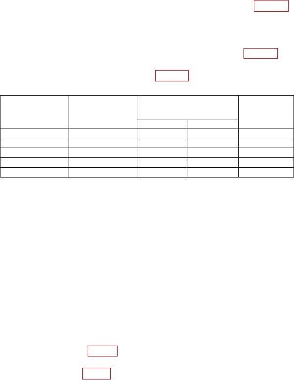
Table 17. Distortion, Incidentals, and Residuals
Test instrument
Audio analyzer
Test description
frequency
Audio analyzer
/measuring
(GHz)
receiver
Frequency
Level
maximum
Pct. Dist @ 1kHz
3.9
1000
.7
8
Inc. FM @ 3.9 GHz
3.9
10000
.425
10000
Inc. FM @ 6.2 GHz
6.2
-----
-----
10000
Inc FM @ 12.3 GHz
12.3
-----
-----
10000
Inc. FM @ 18 GHz
18
-----
-----
10000
(22) Disconnect equipment setup.
b. Adjustments
(1) Remove TI top cover.
(2) Press TI keys as listed in (a) through (g) below:
RCL 0.
(a)
ALC INTERNAL to on.
(b)
FREQUENCY 1, 6, ., 6, and GHz.
(c)
Adjust OUTPUT LEVEL to 10 dB.
(d)
RF OUTPUT to on.
(e)
MTR LVL to on.
(f)
AM 100%.
(g)
(3) Set the audio analyzer to produce a 1 kHz, 1.06 V output with 600
output
impedance, then select special function 17.
(4) Set measuring receiver for an AM measurement and + PEAK detector.
(5) Adjust A1A3R83 (fig. 10) for an indication of 73.0% AM on the measuring
receiver (R).
(6) Adjust A1A6R84 (fig. 10) until TI meter indicates 75% on middle scale of output
meter (R).
22