
TB 9-6625-2155-24
(e) TRIGGER Source to 2.
(f) TRIGGER Coupling to DC.
(g) TRIGGER Slope to
.
(h) Horizontal sweep speed to 200 nS.
(6) Adjust oscilloscope as required for centered five division pulse as in figure 8.
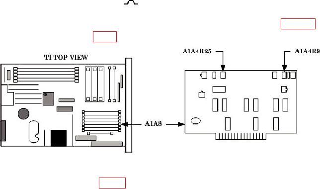
(7) Adjust A1A4R25 (fig. 9) for best pulse shape (R).
Figure 9. A1A4 adjustment locations.
(8) Adjust A1A4R9 (fig. 9) cw until ALC UNLEVEL light is on, then adjust
A1A4R9 ccw until ALC UNLEVEL light is extinguished (R).
(9) Reduce all outputs to minimum.
(10) Replace TI top cover.
13. Amplitude Modulation
a. Performance Check
(1) Connect TI RF OUTPUT to measuring receiver power sensor.
(2) Connect audio analyzer OUTPUT HI to TI AM IN.
(3) Press TI keys as listed in (a) through (e) below.
RCL 0.
(a)
Adjust OUTPUT LEVEL for -13 dB.
(b)
ALC INTERNAL on.
(c)
RF OUTPUT on.
(d)
FREQUENCY, 16.6, GHz.
(e)
(4) Set audio analyzer as listed in (a) through (d) below.
PRGM 99 ENTER RCL.
(a)
(b)
600 output.
(c)
Source frequency 1 kHz.
(d)
Source level 0.7 V.
20