
TB 9-6625-2155-24
(a) Source level 20 mV.
(b) LEVEL STEP 0.1mV.
(c) Source Frequency 100 kHz.
(15) Set measuring receiver to measure frequency modulation, with + PEAK
detector, no filters.
(16) Use the measuring receiver to measure the distortion of the FM 100 kHz signal
Verify that the level indicates less than the maximum listed in table 20.
(17) Set the TI frequency to 2 GHz.
(18) Press TI FM DEVIATION 1 MHz.
(19) Set audio analyzer to produce a 0.707 V signal output.
(20) Set measuring receiver to measure AM with +PEAK detector.
(21) Measuring receiver will indicate less than the maximum limit listed in table 20.
(22) Set TI frequency to next setting listed in table 20 and repeat (21).
(23) Repeat (22) above for remaining TI frequencies listed in table 20.
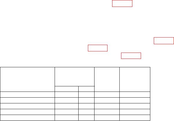
Table 20. Distortion and Incidentals
Measuring
receiver
Test
indication
instrument
Audio analyzer
frequency
(GHz)
Test description
Maximum (%)
Frequency Level
Pct.
Dist.
@ 100
kHz
100000
.020
4
5
Inc.
AM
@
2
GHz
2
5
Inc.
AM
@
6.7
GHz
6.7
5
Inc.
AM
@ 12.4
GHz
12.4
5
Inc.
AM
@ 18
GHz
18
5
(24) Disconnect all equipment.
b. Adjustments
(1) Remove TI top cover.
(2) Press TI keys as listed in (a) through (g) below:
(a) RCL 0.
(b) ALC INTERNAL to on.
(c) FREQUENCY 1, 5, and GHz.
(d) Adjust OUTPUT LEVEL to 0 dB.
(e) RF OUTPUT to on.
(f) MTR FM to on.
(g) FM DEVIATION MHz .1 on.
(3) Set the audio analyzer to produce a 100 kHz, 0.01 V LEVEL STEP size, 1.414 V
output with 600 output impedance, then select special function 17.
25