
TB 9-6625-2155-24
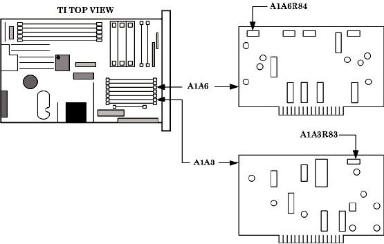
Figure 10. AM adjustment locations.
(7) Reduce all outputs to minimum.
(8) Replace TI top cover.
14. Frequency Modulation
a. Performance Check
(1) Connect TI RF OUTPUT to measuring receiver power sensor.
(2) Connect audio analyzer OUTPUT HI to TI FM IN.
(3) Press TI keys as listed in (a) through (g) below.
RCL 0.
(a)
OUTPUT LEVEL for 0 dB.
(b)
ALC INTERNAL on.
(c)
RF OUTPUT on.
(d)
FREQUENCY, 15.0, GHz.
(e)
MTR FM.
(f)
FM DEVIATION .1 MHz.
(g)
(4) Set audio analyzer as listed in (a) through (f) below.
PRGM 99 ENTER RCL.
(a)
SPCL 17 ENTER.
(b)
(c)
50 output.
(d)
Source frequency 100 kHz.
23