
TB 9-6625-2155-24
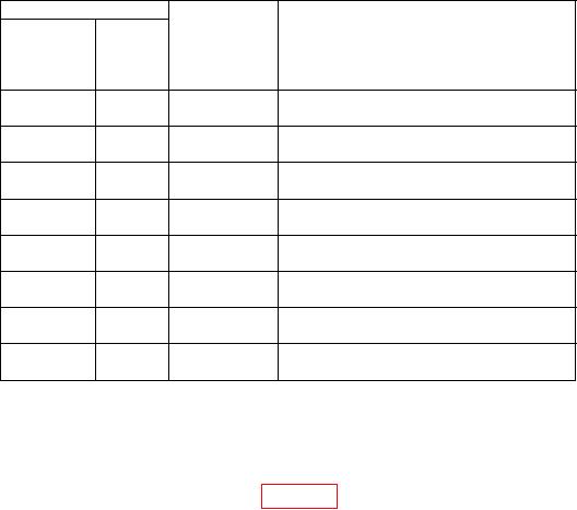
Table 14. Pulse Modulation Overshoot and Undershoot Check - Continued
Test instrument
Synthesized
signal
generator
Frequency
Level
(GHz)
(dB)
Description
(GHz)
12.290
0
12.340
Overshoot Undershoot @ 12.29 GHz
0dBm
12.300
3
12.350
Overshoot Undershoot @ 12.3 GHz
+3dBm
12.300
-10
12.350
Overshoot Undershoot @ 12.3 GHz
-10dBm
12.300
0
12.350
Overshoot Undershoot @ 12.3 GHz
0dBm
18.000
3
18.050
Overshoot Undershoot @ 18.0 GHz
+3dBm
18.000
-10
18.050
Overshoot Undershoot @ 18.0 GHz
-10dBm
18.000
0
18.050
Overshoot Undershoot @ 18.0 GHz
0dBm
1
18.000
8
18.050
Overshoot Undershoot @ 18.0 GHz
8dBm
1Remove
6 dB attenuator pad before adjusting output level to 8 dB.
(9) D i s c o n n e c t e q u i p m e n t s e t u p .
b. Adjustments
(1) Connect equipment as shown in figure 7. Remove TI top cover.
(2) Press TI keys as listed in (a) through (g) below.
RCL, 0.
(a)
FREQUENCY, 2, and GHz.
(b)
OUTPUT LEVEL to 3 dB.
(c)
RF OUTPUT to on.
(d)
ALC INTERNAL to on.
(e)
AUTO PEAK to on.
(f)
PULSE and NORMAL.
(g)
(3) Set the synthesized signal generator to produce a 2.050 GHz signal at 8 dBm
and turn on the RF OUTPUT.
(4) Reset the pulse generator then set to produce a 1 MHz pulse train with a width
of 100 ns, VHI of 5 and VLO of 0, and turn the output on.
(5) Press oscilloscope controls as listed in (a) through (h) below:
Vertical 1 Input to 50 (lit).
(a)
Vertical 1, scale to 20 mV.
(b)
Vertical 2 Input to 50 (lit).
(c)
TRIGGER Sweep to Auto.
(d)
19