
TB 9-6625-2155-24
Table 13. 18 GHz Output Level Test - Continued
Test
instrument
output level
Min
Max
-30
-33
-27
-40
-43
-37
-50
-53
-47
-60
-63
-57
-70
-74.5
-65.5
-80
-84.5
-75.5
-90
-94.5
-85.5
b. Adjustments
(1) Remove TI protective covers.
(2) Press TI FREQUENCY, 2 ,GHz keys and adjust the output level to 3 dB.
(3) Set the measuring receiver to measure tuned power at 2 GHz in a LOG mode.
(4) Press number 6 pushbutton on the TI.
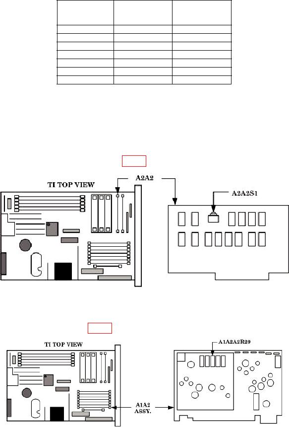
(5) Press service switch A2A2S1 (fig. 4.).
Figure 4. A2A2 board.
(6) Press TI RCL 1.
(7) Adjust A1A2A2R29 (fig. 5) for a measuring receiver indication of 3.0 dBm (R).
Figure 5. A1A2 board.
14