
TB 9-6625-2155-24
(5) Allow spectrum analyzer to sweep signal for approximately 50 seconds then set
spectrum analyzer as listed in (a) through (d) below.
Marker, Off.
(a)
View/Trace, Trace 1, View.
(b)
Marker, Delta, to 1 kHz.
(c)
Marker, More, Function, Marker Noise.
(d)
(6) Spectrum analyzer Mkr
will indicate less than or equal to the minimum
indication listed in table 5.
(7) Repeat technique of (2) through (6) above for remaining frequencies listed in
Table 5. Side Band Phase Noise 1 kHz Removed
Spectrum analyzer
Test instrument
indication
(dB)
minimum ( )
(GHz)
5.999
-62.5
12
-62.5
18
-62.5
b. Adjustments. No adjustments can be made.
10. Harmonics, Subharmonics, Multiples and Non-harmonic Spurious Signals
a. Performance Check
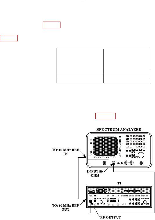
(1) Connect equipment as shown in figure 3 below.
Figure 3. Harmonic, sub harmonic, multiples and non-harmonic spurious hookup.