
TB 9-6625-2162-24
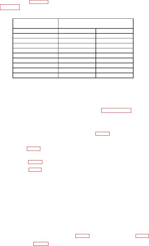
(6) Adjust FREQ 8.4 TO 10.0 GHz COARSE and FINE controls for TI display
indications as listed in table 3. If measuring receiver indications are not within limits
specified in table3, perform b below.
Table 3. Output Frequency
Measuring receiver indications
Test instrument
(MHz)
Display indications
Min
Max
8400
8399
8401
8600
8599
8601
8800
8799
8801
9000
8999
9001
9200
9199
9201
9400
9399
9401
9600
9599
9601
9800
9799
9801
10,000
9999
10,001
(7) Set all outputs to minimum and disconnect equipment setup.
b. Adjustments
NOTE
The TI controls must be positioned IAW paragraph 7 d and 8
a (1) and (2) completed before performing (1) through (14)
below.
(1) Connect multimeter to D/A REF test point (fig. 1) and chassis ground.
(2) Press E on keyboard until display indicates 2.
(3) Adjust VR2 (fig. 1) for 10.20 0.02 V dc multimeter indication (R).
(4) Disconnect multimeter from D/A REF test point and chassis ground and
reconnect between TP1 (fig. 2) and chassis ground.
(5) Adjust VR1 (fig.2) until multimeter indicates voltage listed on label affixed to
GUNN oscillator (R).
(6) Disconnect multimeter from TI.
(7) Press R on keyboard and wait for display to go blank.
(8) Press E on keyboard and wait for completion of self-test.
NOTE
If self-test should fail in (8) above press R to advance past
failing condition.
(9) Press E on keyboard until display indicates 3.
(11) Adjust VR12 (fig. 1), if necessary, to obtain a frequency counter indication
between 3.074 and 3.230 MHz. Record frequency counter indication.
(12) Press E on keyboard until display indicates 4.
6