
TB 9-6625-2164-24
cl. Remove all connections from TI.
8. Vertical Gain
a. Performance Check
(1) Press MENU/TEST, MEMORY DISPLAY 4, 5, 6 and MENU/TEST pushbuttons.
(2) Press TRIGGERING/COUPLING HF REJ pushbutton.
(3) Set VOLTS/DIV switch to 10 mV and TIME/DIV to 200 s.
(4) Connect oscilloscope calibrator SOURCE/MEASURE CHAN 1 output to CH 1.
(5) Press oscilloscope calibrator VOLTAGE key and set for a frequency of 1 kHz
and amplitude for 50 mV.
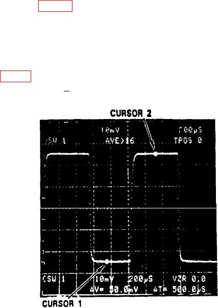
(6) Press f (function) and CURSORS
ON pushbutton and position CURSORS 1
and 2 as shown in figure 6.
(7) Adjust CH 1 AQR GAIN for CURSOR readout of V=50 mV.
(8) Adjust oscilloscope calibrator knob located below the EDIT FIELD key for 5
divisions displayed on TI crt. Displayed err on oscilloscope calibrator will indicate 2
percent and TI V readout will indicate between 49.0 and 51.0 mV.
(9) Adjust TI settings and oscilloscope calibrator VOLTAGE output settings as
listed in table 3. At each setting, verify TI V readout is within limits specified and vertical
deflection is as specified + 2 percent.
Figure 6. CURSORS 1 and 2 used to measure p-p voltage.