
TB 9-6625-2164-24
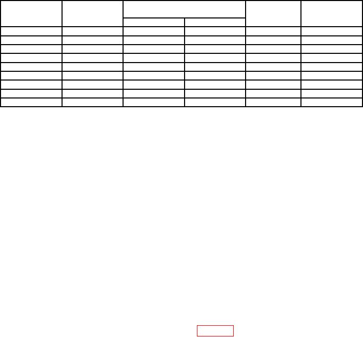
Table 3. Vertical Gain
VOLTS/DIV
Oscilloscope
TI display readout
TI
Oscilloscope
V
switch
calibrator
vertical
calibrator
settings
output
err display
deflection
Min
Max
5 mV
20 mV
19.6
mV
20.4
mV
4
2%
20 mV
0.1 V
98.0 mV
102.0
mV
5
2%
50 mV
0.2 V
196
mV
204
mV
4
2%
100 mV
0.5 V
490
mv
510
mV
5
2%
200 mV
1.0 V
0.98 V
1.02
V
5
2%
500 mV
2.0 V
1.96
V
2.04
V
4
2%
1V
5.0 V
4.90
V
5.10
V
5
2%
2V
10 V
9.80
V
10.20
V
5
2/o
5 V1
20 V
19.60
V
20.40
V
4
2%
1Do
not change settings after this step.
(10)Adjust CH 1 VARIABLE VOLTS/ DIV control fully ccw. TI display waveform
will not exceed 1.6 divisions in amplitude. TI display V readout will be less than 8.0 V
and > sign will appear on TI display.
(11)Adjust CH 1 VARIABLE VOLTS DIV control fully cw.
(12)Press AQR MODE CH 2 2 pushbutton and repeat (3) through (10) above for CH 2.
(13)Remove all connections from TI.
b. Adjustments. No adjustments can be made.
9. Vertical Linearity
a. Performance Check
(1) Press MENU/TEST, MEMOR DISPLAY 4, 5, 6 and MENU/TEST pushbuttons.
(2) Press f (function) and CURSOR ON pushbuttons.
(3) Set CH 1 VOLTS/DIV switch to 20 mV.
(4) Set TIME/DIV switch to 200 s.
(5) Connect oscilloscope calibrator SOURCE/MEASURE CHAN 1 output TI CH 1
input and set oscilloscope calibrator frequency for 1 kHz and output amplitude to 50 mV.
(6) Adjust CURSORS 1 and 2 as shown in figure 7.
(7) Press AVE N pushbutton.
(8) Adjust CH 1 POSITION control to move 2 division display over the entire
graticule area. The CURSOR readout display should not vary more than 2.4 mV.
(9) Press AQR MODE CH 2 2 pushbutton.
(10) Connect oscilloscope calibrator SOURCE/MEASURE CHAN 1 output to TI CH 2
input and set CH 2 VOLTS/DIV to 20 mV.
(11) Adjust CH 2 POSITION control to move 2 division display over the entire
graticule area. The CURSOR readout display indication should not vary more than 2.4 mV.