
TB 9-6625-2173-24
(3) Adjust horizontal POSITION control and rotate oscilloscope calibrator EDIT
FIELD knob to align 1 time marker per division over center 8 divisions. If oscilloscope
calibrator err display readout does not indicate within r3%, perform b (1) below:
(4) Push SECONDS/DIV CAL control in and set SECONDS/DIV switch to 1 Ps.
(5) Set oscilloscope calibrator MARKER output to 1 Ps.
(6) Adjust horizontal POSITION control and rotate oscilloscope calibrator EDIT
FIELD knob to align 1 time marker per division over the center 8 divisions. If oscilloscope
calibrator err display readout does not indicate within r2%, perform b (2) below.
(7) Set SECONDS/DIV switch to .2 Ps.
(8) Set oscilloscope calibrator MARKER output to 0.2 Ps.
(9) Adjust horizontal POSITION control and rotate oscilloscope calibrator EDIT
FIELD knob to align 1 time marker per division over center 8 divisions. If oscilloscope
calibrator err display readout does not indicate within r3%, perform b (2) below.
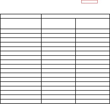
(10) Repeat technique of (7) through (9) above for oscilloscope calibrator and TI
SECONDS/DIV switch settings and indications listed in table 4. Oscilloscope calibrator
err display will indicate within percent of error specified.
Table 4. Fast Timing
Test instrument
Oscilloscope calibrator
SECONDS/DIV
MARKER
err
switch settings
output
(r)
3
0.5
.5
Ps
P
2
2
2
Ps
P
2
5
5
Ps
P
2
10
10
Ps
P
2
20
20
Ps
P
2
50
50
Ps
P
0.1
m
0.1
ms
2
0.5
m
0.5
ms
2
1
m
1
ms
2
2
m
2
ms
2
5
m
5
ms
2
m1
10
10
ms
2
20
m
20
ms
2
50
m
50
ms
2
0.1
s
0.1
s
3
0.2
s
0.2
s
3
0.5
s
0.5
s
3
1Press
and release COUPL AUTO pushbutton to normal.
b. Adjustments
NOTE
Interaction exists between adjustments in (1) and (2) below.
Repeat as necessary for best compromise.
14