
TB 9-6625-2173-24
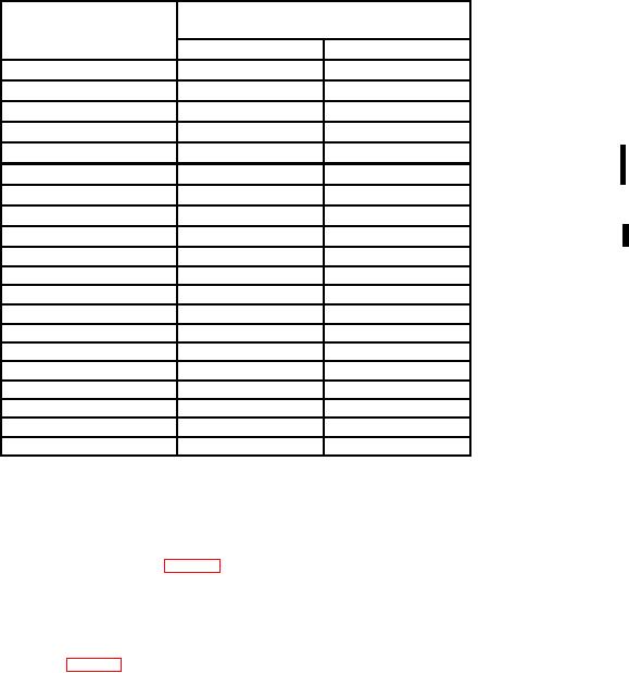
Table 8. Mag Sweep Timing
Test instrument
Oscilloscope Calibrator
SECONDS/DIV
switch settings
Marker
err r
50
ns
5
ns
4
10
ns
4
0.1 Ps
20
ns
3
0.2 Ps
50
ns
3
0.5 Ps
3
1
Ps
0.1 Ps
3
2
Ps
0.2 Ps
3
5
Ps
0.5 Ps
3
10
Ps
1
Ps
3
20
Ps
2
Ps
3
50
Ps
5
Ps
0.1 ms
3
10
Ps
0.5 ms
3
50
Ps
1
ms
0.1 ms
3
2
ms
0.2 ms
3
5
ms
0.5 ms
3
10
ms
1
ms
3
20
ms
2
ms
3
50
ms
5
ms
4
0.1 s
10
ms
4
0.2 s
20
ms
4
b. Adjustments
(1) Rotate oscilloscope calibrator EDIT FIELD for an err display of 0.0%. Adjust
horizontal POSITION control to align 2d time marker with 2d vertical graticule line.
(2) Adjust R1167 X1 GAIN (fig. 6) for 1 marker per division. The 2d and 10th
markers must align with the 2d and 10th vertical graticule lines (R).
(3) Rotate oscilloscope calibrator EDIT FIELD for an err display of 0.0%. Adjust
horizontal POSITION control to align 2d marker with 2d vertical graticule line.
(4) Adjust C1238 (fig. 6) for 1 marker per division. The 2d and 10th markers must
align with the 2d and 10th vertical graticule lines (R).
NOTE
Steps b (5) through (9) below are prerequisite steps that need
to be performed at this time in addition to the requirements
within steps b (10) through (15).
(5) Set PULL X10 HORIZ MAG switch to in position.
(6) Set SECONDS/DIV switch to .1 m and oscilloscope calibrator MARKER output
to 0.5ms.
(7) Adjust INTEN, FOCUS, TRIGGERING LEVEL, and CH 1 POSITION
controls as necessary for a stable, centered display.
CHANGE 1 27