
TB 9-6625-2173-24
(8) Press in and hold DISPLAY TRIG VIEW pushbutton and adjust INTEN and
FOCUS controls for suitable viewing.
(9) While holding DISPLAY TRIG VIEW pushbutton in, verify a stable display can
be obtained by adjusting the TRIGGERING LEVEL control.
b. Adjustments
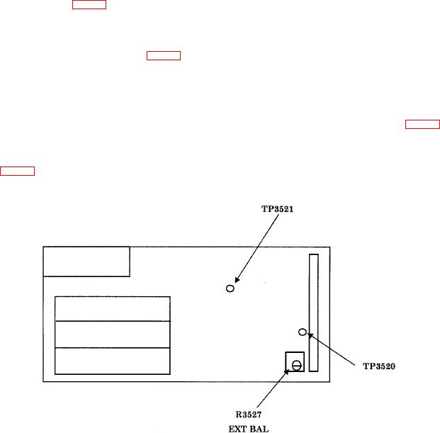
(1) Set multimeter to measure 2 V dc fullscale and connect HI input to TP3520 and
LO input to TP3521 (fig. 9).
(2) Press the CPLG AC pushbutton in and set the TRIGGERING SOURCE
switch to INT.
(3) Adjust R3527 EXT BAL (fig. 9) for 0 V r10 mV. Disconnect the multimeter (R).
(4) Set the SECONDS/DIV switch to 2 m and TRIGGERING SOURCE switch
to LINE.
(5) Press the TRIGGERING MODE AUTO pushbutton in.
(6) Press and hold DISPLAY TRIG VIEW pushbutton and adjust R3336 (fig. 7) so
the start of waveform trace is at horizontal graticule center line (R).
(7) Set TRIGGERING SLOPE switch to and compromise final adjustment of
R3336 (fig. 7) between display starts of both + and SLOPE switch settings while pressing
the TRIG VIEW pushbutton in.
Figure 9. Trigger switch board.
(8) Set TRIGGERING LEVEL control fully ccw.
24