
TB 9-6625-2182-24
MODULATION SOURCE - EXT DC.
(h)
MOD - FREQ.
(i)
DATA - 1 kHz.
(j)
SHIFT.
(k)
ENTRY MOD OUT.
(l)
DATA ( +1V).
(m)
(3) Set measuring receiver to measure AM with a 300 Hz high pass filter and a
3 kHz low pass filter.
(4) Measuring receiver will indicate within limits specified in table 17.
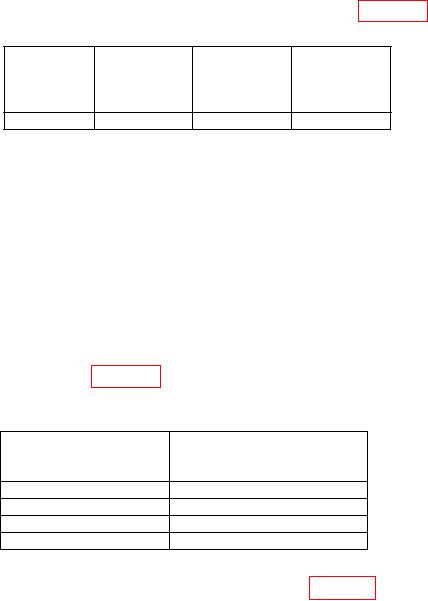
Table 17. Incidental AM
Measuring
Peak
receiver
Carrier
Modulation
deviation
indication
frequency
rate
kHz
<%
1 GHz
1 kHz
20
0.3
(5) Set measuring receiver to measure FM with all filters off.
(6) Press TI pushbuttons as listed in (a) through (f) below:
ENTRY - FREQ.
(a)
DATA - 250 MHz.
(b)
ENTRY - AMPTD.
(c)
DATA - (+10 dBm).
(d)
ENTRY - FM.
(e)
DATA - 300 kHz.
(f)
(7) Press ENTRY MOD FREQ pushbutton and enter DATA modulated
frequency for each row listed in table 18. Distortion measurement on measuring receiver
will indicate within limits specified.
Table 18. Audio FM Distortion
Test instrument
Measure receiver distortion
DATA
indications
modulated frequency
(%)
20 Hz
2
400 Hz
2
1 kHz
2
100 kHz
2
(8) Perform steps (a) through (d) below for each row in table 19:
(a) Press TI ENTRY - FREQ pushbutton and enter DATA carrier frequency as listed.
(b) Press TI ENTRY MOD FREQ pushbutton and enter DATA modulation
frequency as listed.
(c) Press TI ENTRY FM pushbutton and enter DATA frequency modulation
as listed.
15