
TB 9-6625-2182-24
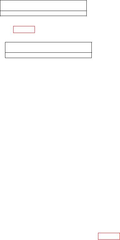
Table 12. Pulse Modulation Risetime
Oscilloscope indication
< u Sec
0 .5
(15) Using oscilloscope measurement techniques, verify that the falltime of displayed
envelope is within limits listed in table 13.
Table 13. Pulse Modulation Falltime
Oscilloscope
< u Sec
0.5
(16) Press RF OFF/ON pushbutton to OFF.
(17) Disconnect pulse generator and oscilloscope from circuit.
b. Adjustments. No adjustments can be made.
15. Amplitude Modulation
a. Performance Check
(1) Connect measuring receiver with sensor module to TI OUTPUT RF.
(2) Connect OUTPUT MOD to INPUT AM.
(3) Press TI pushbuttons as listed in (a) through (m) below.
INSTR PRESET.
(a)
ENTRY - FREQ.
(b)
DATA - 1 GHz.
(c)
ENTRY - AMPTD.
(d)
DATA - (+13 dBm).
(e)
ENTRY - AM.
(f)
DATA - 30%.
(g)
MODULATION SOURCE - EXT DC.
(h)
ENTRY MOD FREQ.
(i)
DATA - 1 kHz.
(j)
SHIFT.
(k)
ENTRY MOD OUT.
(l)
DATA ( +1V).
(m)
(4) Set measuring receiver to measure FM with a 300 Hz high pass filter and a 3
kHz low pass filter.
(5) Measuring receiver will indicate within limits specified in table 14.