
TB 9-6625-2182-24
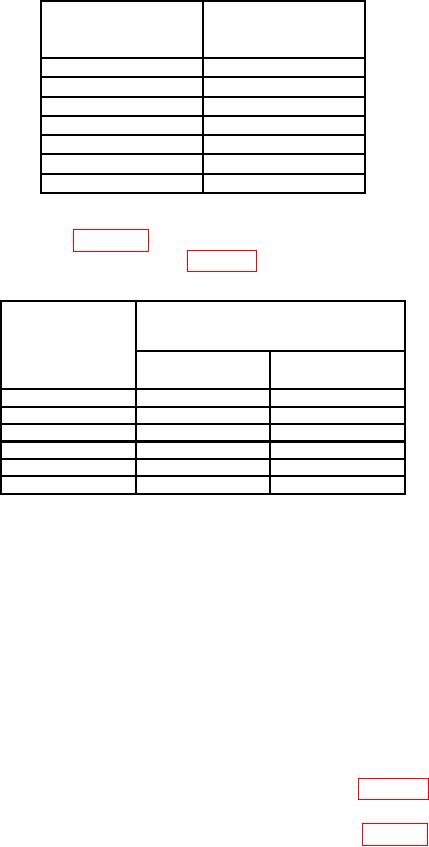
Table 22. Internal Oscillator Distortion
Audio analyzer
Test instrument
distortion indications
DATA
<(%)
modulated frequency
20
Hz
0.02
100
Hz
0.02
1
kHz
0.02
10
kHz
0.02
15
kHz
0.02
30
kHz
0.15
100
kHz
0.15
(4) Press TI ENTRY MOD FREQ pushbutton and enter DATA modulated
frequency for each row in table 23. Set audio analyzer to measure frequency. Audio
analyzer will indicate within limits listed in table 23.
Table 23. Internal Oscillator Frequency
Test instrument
Audio analyzer
DATA
indications
modulated
(Hz)
settings
Min
Max
20
Hz
19.6
20.4
100
Hz
98
102
1
kHz
980
1020
10
kHz
9800
10200
50
kHz
49000
51000
100
kHz
98000
102000
(5) Disconnect audio analyzer from TI OUTPUT MOD.
b. Adjustments. No adjustments can be made.
19. Power Supply
a. Performance Check
NOTE
Do not perform power supply check if all other parameters are
within tolerance.
(1) Deenergize TI and remove top cover.
(2) Set POWER switch ON and allow sufficient time to warm-up.
(3) Connect multimeter HI INPUT to test points listed in table 24 and connect LO
INPUT to chassis ground.
(4) If multimeter does not indicate within specifications listed in table 24, perform b below:
(5) Remove test leads and deenergize TI.