
TB 9-6625-2211-24
15. Variable Gating, Mode 4 Challenge and GTC Trigger Accuracy
a. Performance Check
(1) Position controls as listed in 7 d. above.
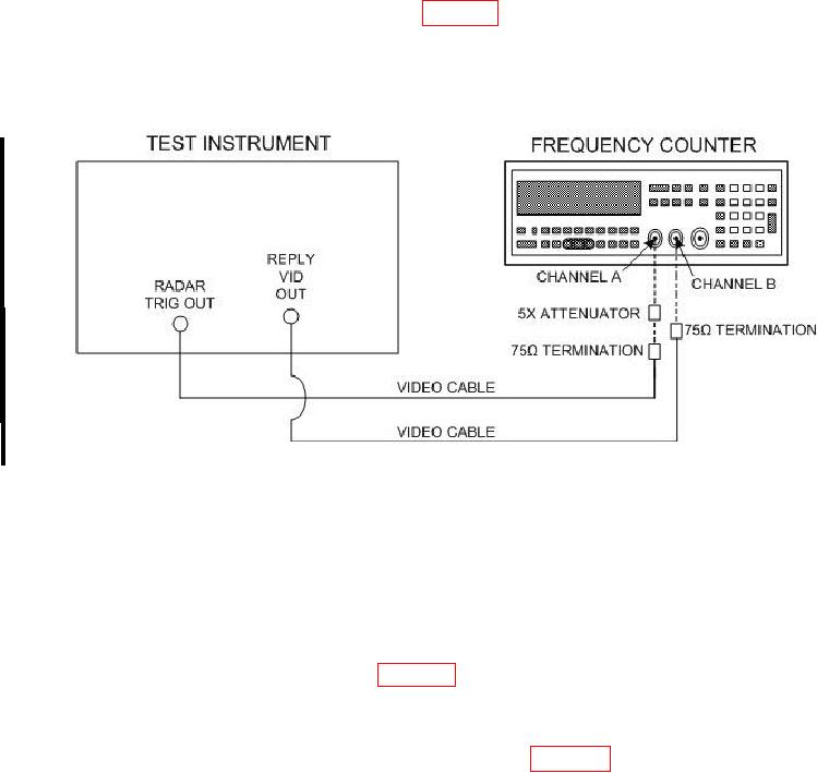
(2) Connect equipment as shown in figure 6.
(3) Set REPLIES MODULATION SEL switch to M4-1P. Adjust frequency
counter controls for ratio measurement. The frequency counter will indicate between 0.990
and 1.010.
Figure 6. Variable gating - equipment setup.
NOTE
In (4) and (5) below after the TI settings are changed, press
frequency counter RESET pushbutton and wait for two gating
periods before making the measurement.
(4) Set REPLIES GATING PASS switches and REPLIES GATING INHIB
switches to the first setting listed in table 12. The frequency counter will indicate within
limits specified.
(5) Repeat technique of (4) above for remaining REPLIES GATING PASS and
REPLIES GATING INHIB switch settings listed in table 12. Frequency counter will
indicate as specified.
22 CHANGE 1