
TB 9-6625-2215-24
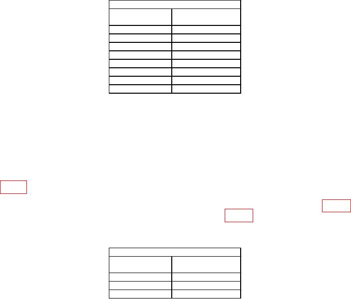
Table 7. Sensitivity RANGE MHz 50.
Function generator output
Frequency
Amplitude limits
(Hz)
(mV)
≤ 100
10
≤ 100
100
≤ 100
1000
≤ 100
10000
≤ 100
100000
≤ 100
1000000
≤ 100
10000000
≤ 100
1
50000000
If out of tolerance and no adjustment was
1
performed in (8) above, perform b below.
(10) Set RANGE MHz switch to 500.
(11) Substitute signal generator for function generator.
to obtain the minimum level that will produce a stable indication of applied frequency on
measuring system. If signal generator amplitude exceeds limit specified in first row of
table 8 and no adjustment was previously made, perform b below.
(13) Repeat technique of (12) above for signal generator frequencies listed in table 8.
If signal generator amplitude exceeds limit specified in table 8 and no adjustment was
previously made, perform b below.
Table 8. Sensitivity RANGE MHz 500.
Signal generator output
Frequency
Amplitude limits
(MHz)
(mV)
≤ 100
100
≤ 100
300
≤ 100
500
b. Adjustments
(1) Remove bottom cover from TI.
(2) Connect signal generator to TI 50 Ω input.
(4) Set TI GATE TIME SEC switch to .1 and RANGE MHz switch to 500.
(5) Adjust A1R6 (located bottom side lower center of board A1) to obtain stable
indication of applied frequency on measuring system.
(6) While reducing signal generator amplitude, adjust A1R6 to obtain
maximum sensitivity.
13