
TB 9-6625-2258-24
(16) Repeat (8) through (15) above until both +7.0 and -2.9 dBm are within tolerance.
(17) Disconnect measuring receiver power sensor from RF OUTPUT 50 .
(18) Press POWER pushbutton to OFF position.
(19) Remove TI top cover and replace TI board cover screw holding CCA boards.
(20) Replace and secure TI top cover.
(21) Press POWER pushbutton to ON position.
Output Attenuator Test
a. Performance Check
(1) Press RESET key.
to spectrum analyzer INPUT 50 .
(2) Connect RF OUTPUT 50
(3) Press LEVEL key and set LEVEL display to 0.0 dBm by pressing 0 with DATA
ENTRY keys and then by pressing GHZ/dBm/SEC DATA ENTRY key.
(4) Press FREQUENCY RANGE CW F1 key and set F1 M3 display to 2.000 GHz
by pressing 2 with DATA ENTRY key and then by pressing GHz/dBm/SEC DATA
ENTRY key.
(5) Adjust spectrum analyzer controls to view TI fundamental signal near center
frequency graticule and top of fundamental referenced to top graticule on spectrum
analyzer display.
NOTE
Adjust spectrum analyzer controls as necessary to display a
marker pair with reference marker at peak of fundamental
frequency for (6) through (8) below.
(6) Set LEVEL display to -10.0 dB by pressing -10 with DATA ENTRY keys and
then by pressing MHz/dB/mS DATA ENTRY key.
(7) Spectrum analyzer will indicate within limits in first row of table 8.
(8) Repeat technique of (6) and (7) above for remaining TI levels in table 8.
Spectrum analyzer will indicate within limits listed in table 8.
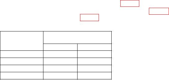
Table 8. Attenuator Test @ 2 GHz
Test instrument
Spectrum analyzer indication
LEVEL (dBm)
limits (dBm)
Min
Max
-10
-12.6
-7.4
-20
-22.6
-17.4
-30
-32.6
-27.4
-40
-42.6
-37.4