
TB 9-6625-2258-24
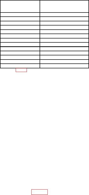
Table 7. Maximum Output Power Test - Continued
Measuring receiver
settings
1
(MHz)
indications
6.0
6000
7.0
7000
8.0
8000
9.0
9000
10.0
10,000
11.0
11,000
12.0
12,000
13.0
13,000
14.0
14,000
15.0
15,000
16.0
16,000
17.0
17,000
18.0
18,000
1Refer
to table 6 for actual multimeter indications values.
(28) Disconnect measuring receiver power sensor from RF OUTPUT 50 .
(29) Press TRIGGER AUTO key.
(30) Press FREQUENCY RANGE Fl-F2 key.
(31) Press F1 M3 key and set F1 M3 display to 18.000 GHz by pressing 18 with
DATA ENTRY keys and then by pressing GHz/ dBm/SEC DATA ENTRY key.
(32) Press F2 M6 key and set F2 M6 display to 26.500 GHz by pressing 26.5 with
DATA ENTRY keys and then by pressing GHZ/ dBm/SEC DATA ENTRY key.
(33) Press SWEEP TIME key and set SWEEP display to 1.0 s by pressing 1 with
DATA ENTRY key and then by pressing GHZ/ dBm/SEC key.
(34) Press LEVEL key and set LEVEL display to +7.0 dBm by pressing 7 with
DATA ENTRY key and then by pressing GHz/dBm/ SEC DATA ENTRY key.
(35) Connect RF OUTPUT 50
to thermistor mount No. 1 of power meter.
(36) Rotate INCR-DECR control cw until UNLEVELED indicator blinks on.
WARNING
Do not exceed +10 dBm indication on power meter.
(37) Slowly rotate INCR-DECR control ccw until UNLEVELED indicator quits
blinking.
(38) Press TRIGGER SWEEP MANUAL key.
(39) Slowly rotate TRIGGER MANUAL SWEEP control cw until multimeter
indicates same value as recorded in table 6 for 20.000 GHz. If power meter lowest
indication is not equal or greater than +7.0 dBm, perform b below.
(40) Press TRIGGER AUTO key.
(41) Press SWEEP TIME key and set dB SWEEP display to 1.0 second by pressing
1 with DATA ENTRY key and then by pressing GHz/dBm/SEC DATA ENTRY key.
21