TB 9-6625-2258-24
(4) Press RESET key and allow TI to warm-up for 30 minutes.
(5) Connect measuring receiver power sensor to RF OUTPUT 50 .
(6) Press FREQUENCY RANGE CW F1 key and set F1 M3 display to 2.050 GHz
by pressing 2.05 with DATA ENTRY keys and then by pressing GHz/dBm/SEC DATA
ENTRY key.
(7) Configure measuring receiver for RF power measurement.
(8) Remove TI top cover.
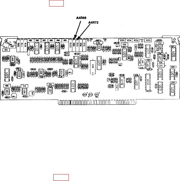
(9) Adjust A4R66 (fig. 4) for a measuring receiver displayed indication between +6.9
and +7.1 dBm.
Figure 4. A4 board - component locations.
(10) Replace TI top cover.
NOTE
Wait 5 minutes before proceeding to (11) below.
(11) Press LEVEL key and set LEVEL display to -2.9 dBm by pressing -2.9 with
DATA ENTRY keys and then by pressing GHz/dBm/SEC DATA ENTRY key.
(12) Remove TI top cover.
(13) Adjust A4R72 (fig. 4) for a measuring receiver RF power display indication
between -2.8 and -3.0 dBm (R).
(14) Replace TI top cover.
NOTE
Wait 5 minutes before proceeding to (15) below.
(15) Press LEVEL key and set LEVEL display to +7.0 dBm by pressing 7 with
DATA ENTRY key and then by pressing GHz/dBm/ SEC DATA ENTRY keys.
23

