
TB 9-6625-2271-40
Table 9. Output Frequency Accuracy
Frequency counter indications (Hz)
Test instrument
SOURCE FREQ
1120/S-10
1121
(Hz)
Min
Max
Min
Max
433.33
433.3157
433.3443
433.3152
433.3448
5444.4
5444.246
5444.554
5444.24
5444.56
6555.5
6554.434
6556.566
6554.428
6556.572
76666
76664.23
76667.77
76664.16
76667.84
87777
87775.12
87778.88
87775.03
87778.97
98888
98886.01
98889.99
98885.91
98890.09
99999
99997.0
100001.0
99996.9
100001.1
140000
139997.6
140002.4
139997.5
140002.5
b. Adjustments
(1) Connect time/frequency workstation OUTPUT 10 MHz to TI rear panel X
CLOCK input.
(2) For 1120-S/10 perform (a) below, for 1121 perform (b) below.
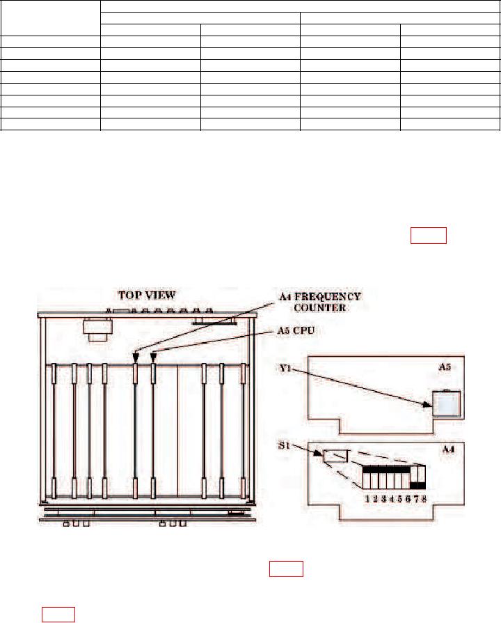
(a) Remove top cover and set A4S1 switch positions 7 and 8 (fig. 5) to open
(down) and press LCL INIT key.
(b) Press SPCL 35, and ENTER.
Figure 5. Time base accuracy - adjustment locations.
(3) Remove cover screw from A5 CPU Y1 (fig. 5) and adjust internal slotted screw
for a TI indication of 10000.00 kHz ( 1 count) (R).
(4) For 1120-S/10 only, reset A4 FREQUENCY COUNTER S1 switch positions 7
and 8 (fig. 5) to the closed (up) position.
15