
TB 9-6625-2271-40
(4) Press TI SOURCE FREQ key and enter 40 Hz using DATA ENTRY keys. If
TI indication is not <.01 percent, perform b below.
(5) Repeat (4) above using TI SOURCE FREQ settings listed in table 12.
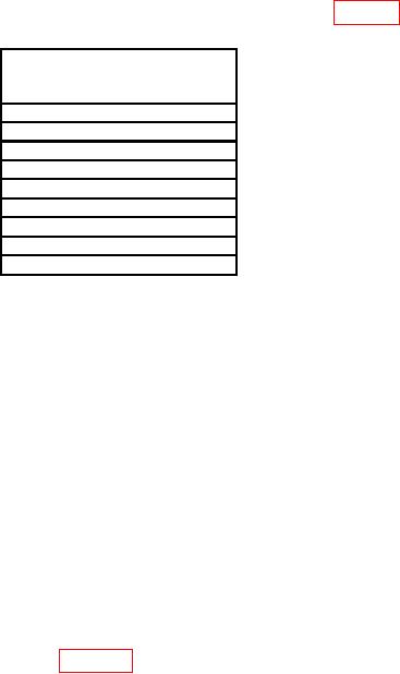
Table 12. Output Distortion
Test instrument
SOURCE FREQ settings
(Hz)
80
160
320
640
1280
2560
5120
10240
19990
(7) Enter 21 kHz using DATA ENTRY keys. If TI indication is not <0.02 percent,
perform b below.
(8) Enter 42 kHz using DATA ENTRY keys. If TI indication is not <0.02 percent,
perform b below.
(9) Enter 84 kHz using DATA ENTRY keys. If TI indication is not <0.056 percent,
perform b below.
(10) Enter 99 kHz using DATA ENTRY keys. If TI indication is not <0.056 percent,
perform b below.
b. Adjustments. No specific adjustments are provided for the output circuitry of TI.
The adjustments listed in paragraph 12 could cause a failure of this test. If distortion
indications are only slightly high, perform paragraph 12 b then perform paragraphs 12 a
and 15 a.
16. SINAD Measurement Accuracy
a. Performance Check
(1) Connect equipment as shown in figure 7 below.
(2) Press keys and enter values using DATA ENTRY keys as listed in (a) through
(j) below:
LCL INIT.
(a)
SOURCE LEVEL.
(b)
1 V.
(c)
SOURCE FREQ.
(d)
600 Hz.
(e)
SPCL.
(f)
75 ENTER.
(g)
ANALYZER SINAD.
(h)
SPCL.
(i)
10 ENTER.
(j)