
TB 9-6625-2280-40
(6) Set TI POWER switch to ON.
(7) Allow 30 minutes for TI to warm-up and stabilize.
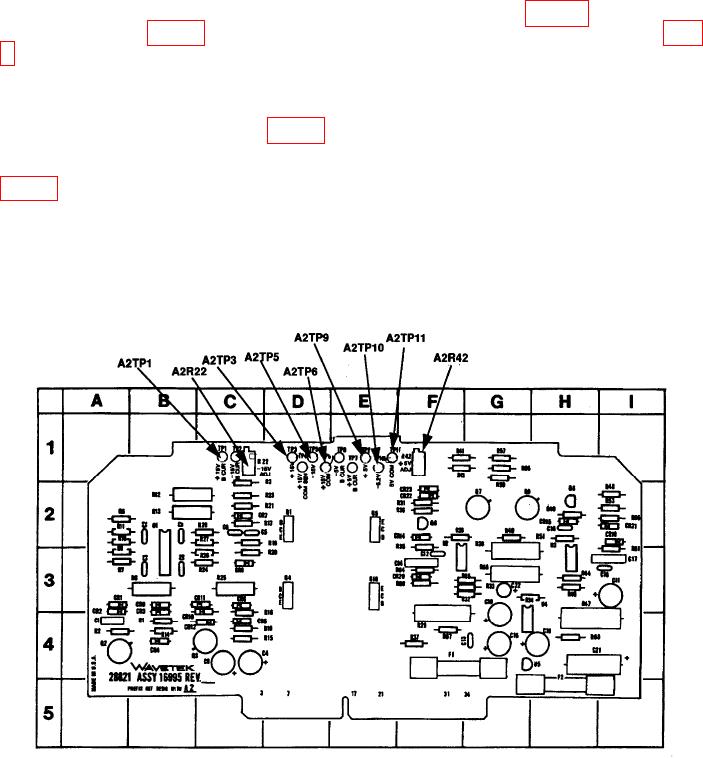
(8) Connect multimeter (dc mode) to test points (refer to figure 4 for test point
5, perform corresponding adjustments listed.
(9) Adjust autotransformer controls from 105 to 125 V ac while observing
multimeter indications. Multimeter indications will be within the limits listed in the
change in voltage (mV) column of table 5.
(10) Repeat (8) and (9) above for remaining power supply voltages (V dc) listed in
(11) Press TI POWER switch to OFF position.
(12) Disconnect TI from equipment setup.
(13) Replace TI top.
Figure 4. Power Supply - Component Locations.
19