
TB 9-6625-2295-24
(6) Repeat technique of (2) (a) and (3) through (5) above for settings listed in table
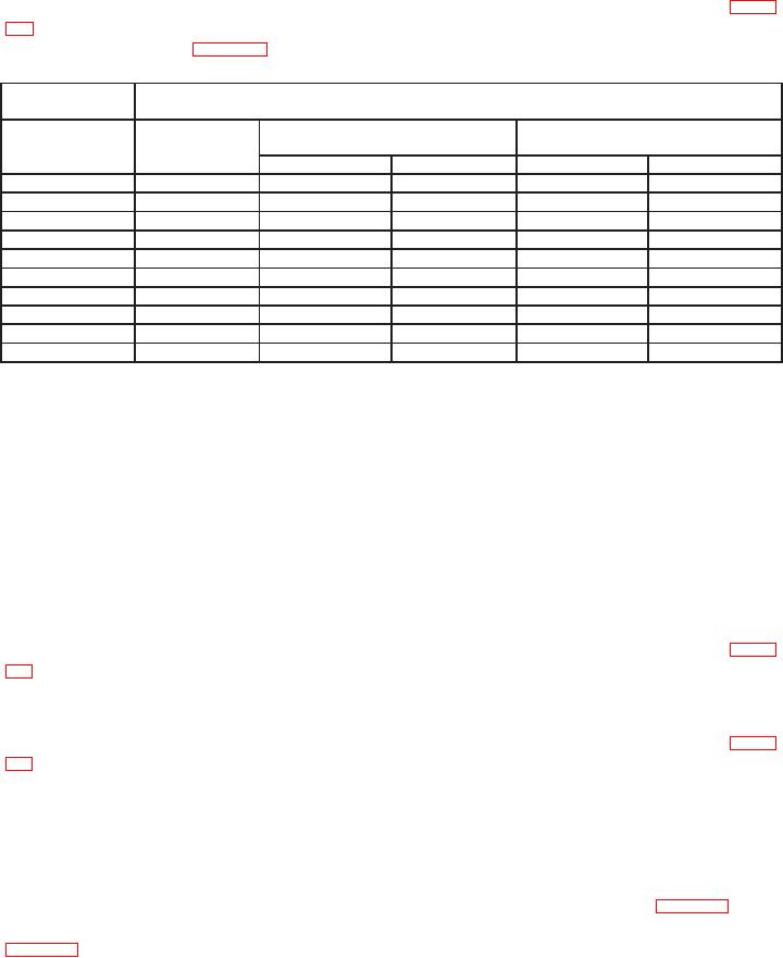
10. If A TRIGGER LEVEL readout indications are not within limits specified in + peak
and - peak columns in table 10, perform b below.
Table 10. Trigger Level 1 M: Input Coupling
calibrator
Test instrument
+ peak
peak
indication
indication
VOLTS/DIV
Output
settings
Min
Max
Min
Max
20 mV
5 mV
16.8 mV
23.2 mV
2.6 mV
2.6 mV
50 mV
10 mV
44
mV
56
mV
4.5 mV
4.5 mV
0.1 V
20 mV
89
mV
111
mV
8.0 mV
8.0 mV
0.2 V
50 mV
178
mV
222
mV
16
mV
16
mV
0.5 V
100 mV
450
mV
550
mV
35
mV
35
mV
1.0 V
200 mV
0.9 V
1.10 V
70
mV
70
mV
2.0 V
500 mV
1.78 V
2.22 V
0.16 V
0.16 V
5.0 V
1.0 V
4.50 V
5.50 V
0.35 V
0.35 V
10.0 V
2.0 V
9.0 V
11.0 V
0.7 V
0.7 V
20.0 V
5.0 V
17.8 V
22.2 V
1.6 V
1.6 V
(7) Set oscilloscope calibrator for a CHAN 1, VOLTAGE mode output of 20 mV at 1
kHz and set TI CH 1 VOLTS/DIV switch to 5 mV.
(8) Pull SEC/DIV knob out and press A/B TRIG pushbutton for B TRIGGER and
press TRIGGER MODE pushbutton for TRIG DLY. Adjust TRIGGER LEVEL for a
stable display.
(9) Adjust ' REF OR DLY POS control for a delay readout of 0.000 ms.
NOTE
Combine steps (10) and (11) below to avoid resetting standards.
(10) Adjust TRIGGER LEVEL control for most positive voltage that produces an
intensified point on waveform display when selecting + and - SLOPE. If B TRIGGER
level readout indication is not within limits specified in + peak column in first row of table
11, perform b below.
(11) Adjust TRIGGER LEVEL control for most negative voltage that produces an
intensified point on waveform display when selecting + and - SLOPE. If B TRIGGER
level readout indication is not within limits specified in -peak column in first row of table
11, perform b below.
NOTE
It may be necessary to reselect A SWP and adjust LEVEL
control for stable sweep before returning to check B SWP
triggering levels in the following table.
(12) Repeat technique of (7) and (9) through (11) above for settings in table 11. If B
TRIGGER level readout indication is not within limits specified in appropriate columns of
table 11, perform b below.
12