
TB 9-6625-2295-24
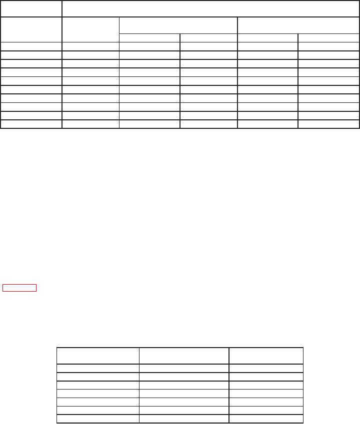
Table 11. Trigger Level 1 M: Input Coupling
Oscilloscope
calibrator
Test instrument
+ peak
peak
indication
indication
VOLTS/DIV
Output
settings
Min
Max
Min
Max
20 mV
5 mV
16.8 mV
23.2 mV
2.6 mV
2.6 mV
50 mV
10 mV
44
mV
56
mV
4.5 mV
4.5 mV
0.1 V
20 mV
89
mV
111
mV
8.0 mV
8.0 mV
0.2 V
50 mV
178
mV
222
mV
16
mV
16
mV
0.5 V
100 mV
450
mV
550
mV
35
mV
35
mV
1.0 V
200 mV
0.9 V
1.10 V
70
mV
70
mV
2.0 V
500 mV
1.78 V
2.22 V
0.16 V
0.16 V
5.0 V
1.0 V
4.50 V
5.50 V
0.35 V
0.35 V
10.0 V
2.0 V
9.0 V
11.0 V
0.7 V
0.7 V
20.0 V
5.0 V
17.8 V
22.2 V
1.6 V
1.6 V
(13) Reduce all outputs to minimum.
(14) Press corresponding pushbuttons for indications listed in (a) through (c) below:
(a) 20 MHz BW LIMIT off.
(b) TRIGGER SLOPE to + (positive) and TRIGGER COUPLING to AC.
(c) TRIGGER MODE to AUTO LVL, TRIGGER SOURCE to VERT CH 1.
(15) Set CH 1 VOLTS/DIV switch to 100 mV and A SWP SEC/DIV switch to 50 Ps
(knobs locked).
(16) Connect oscilloscope calibrator SOURCE/MEASURE CHAN 1 to TI CH 1 and
SOURCE/MEASURE CHAN 2 to TI CH 2 using 50 Ÿ feedthrough terminations.
(17) Set oscilloscope calibrator for a CHAN 1, LEVEL SINE mode output of 50 kHz
and adjust output amplitude for 0.35 division of display on TI.
(18) Adjust TRIGGER LEVEL control for a stable display at all settings listed in
table 12. If a stable display cannot be obtained, perform b below.
NOTE
Set A SWP SEC/DIV switch and press X10 MAG pushbutton
as necessary to obtain a well-defined display of test signal.
Table 12. Channel 1 Trigger Level Frequency Response Stability
Oscilloscope calibrator
Test instrument
Test instrument
TRIGGER COUPLING
output frequency
divisions of display
50
kHz
AC
0.35
50
MHz
AC
0.35
50
MHz
DC
0.35
300
MHz
DC
1
300
MHz
AC
1
500
MHz
AC
1.5
500
MHz
DC
1.5
13