
TB 9-6625-2304-24
11. Load Resistance (10 to 60 m )
a. Performance Check
(1) Remove six screws and washers securing the hinged TI top panel.
(2) Starting with R1, connect equipment as shown in figure 2.
CAUTION
The type of test leads used and improper connection of
calibrator/multimeter to resistor under test can cause out-of-
tolerance indications. Ensure solid contact is made as close to
resistor as possible.
(3) Configure multimeter for most accurate dc voltage measurements.
(4) Set calibrator for a 1.0 A dc output.
Multimeter will indicate within limits
specified in first row of table 5.
(5) Set calibrator output to minimum.
(6) Move calibrator and multimeter connections to next resistor specified in table 5.
Repeat technique of (4) and (5) above for R2 through R8. Multimeter will indicate within
limits specified in table 5.
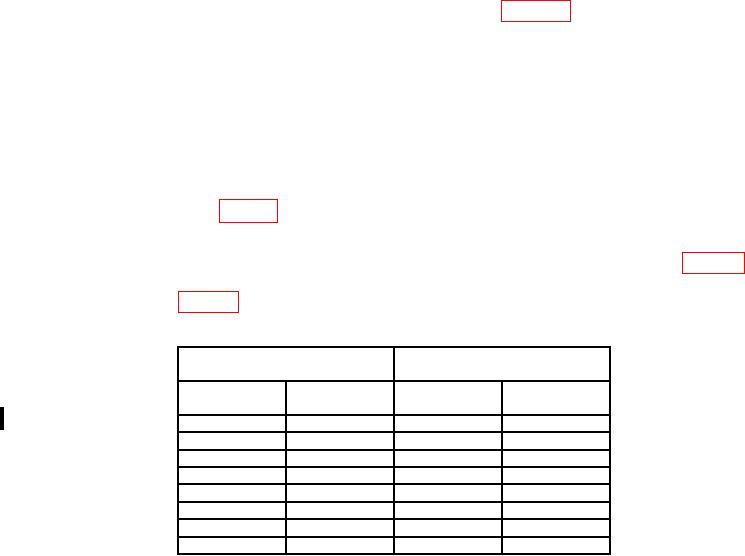
Table 5. Load Resistance
Multimeter indications
Test instrument
(mV dc)
Nominal value
(m )
Resistor
Min
Max
R1
10.0
9.9490
10.0510
R2
10.0
9.9490
10.0510
R3
20.0
19.8980
20.1020
R4
20.0
19.8980
20.1020
R5
20.0
19.8980
20.1020
R6
20.0
19.8980
20.1020
R7
20.0
19.8980
20.1020
R8
60.0
59.7000
60.3000
b. Adjustments. No adjustments can be made.
12. Thermal Converter
a. Performance Check
NOTE
The TI thermal converter will have to be disconnected from the
internal connections (including the T-connector) before
connecting as described in (1) below.