
TB 9-6625-2309-24
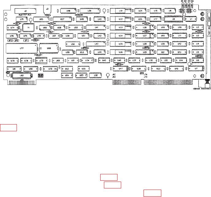
Figure 16. U71 location on DAS 1A2A4 circuit board.
b. Perform (1) through (9) below:
(1) Set ON-OFF switch to OFF.
(2) Remove chassis screw anchoring GROUND STRAP at A/D 1A2A8 circuit board
(3) Remove electrical tie down straps if present.
CAUTION
Twisting coax connector or stretching may damage coax. Pull
straight back and or use flat blade screwdriver to pry coax
connector loose.
(4) Remove coax connector from J1 (fig. 17).
(5) Remove A/D 1A2A8 circuit board (fig. 15).
(6) Install A/D SHORTING PLUG (LPTF-1047) on J1 (fig. 17).
27