
TB 9-6625-2309-24
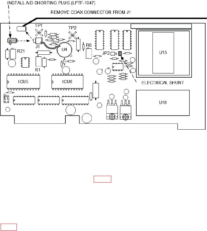
Figure 17. A/D 1A2A8 - adjustment locations.
(7) I n s t a l l A / D e x t e n de r c a r d ( LP T F - 1 0 4 8 ) i n to TI A / D 1 A 2 A8 m o th e r
b o a r d connector.
(8) Install A/D 1A2A8 circuit board on extender card.
(9) Connect GROUNDING STRAP (fig. 15) to TI chassis using jumper wire.
NOTE
Allow 15 minutes for TI to warm-up before making voltage
measurements.
c. Set ON-OFF switch to ON.
d. Connect multimeter negative lead to ICU6, pin 12, and positive lead to ICU6, pin 23
28