
TB 9-6625-2309-24
NOTE
Perform steps in paragraph 12 below only if FOCUS SWCM or
FOCUS LWCM standards have had optical subassembly
repaired/replaced or DG535, digital delay generator, has been
repaired/replaced.
12. Time Insertion Delay Characterization
NOTE
Steps which follow assume TD-260 optical module is presently
installed in TI. Technique of paragraph 12 also applies to TD-
261C and TD-285C optical modules. If removal of optical
module is required, the steps in paragraphs 7 a and b must be
performed to ensure proper sync.
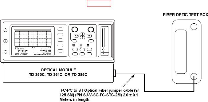
a. Connect equipment as shown in figure 18.
Figure 18. Equipment setup with fiber optic test box used to establish reference cursor position.
b. To change length and resolution perform steps (1) through (8) below:
(1) Press TI HELP pushbutton as required to change to Help Facility screen.
(2) Press MORE softkey.
(3) Press INSTRUMENT SETUP softkey.
(4) Press OTDR SETUP softkey.
(5) Press FIBER LEN/RES softkey.
(6) Adjust CURSOR A control to set new length to 8 km and resolution to 0.5 m.
(7) Press ACCEPT CHANGES softkey.
(8) Press Return to OTDR Mode softkey.