
TB 9-6625-2309-24
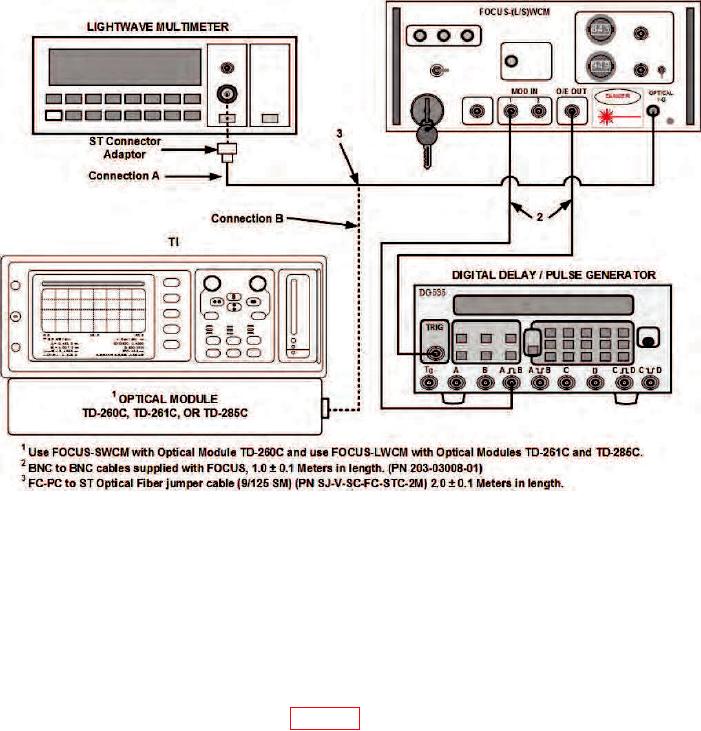
Figure 21. Equipment setup for time insertion delay after fiber test box is removed.
f. Monitor lightwave multimeter and adjust FOCUS-SWCM VAR ATTN 1 control for
-27 0.2 dBm optical power output.
NOTE
When calibrating TD-285C optical module, adjust FOCUS-LWCM
VAR ATTN 1 for -38 0.2 dBm at 1310 nm and 1550 nm.
g. Carefully remove optical fiber jumper cable connector from lightwave multimeter
and connect to fiber connector of TD-260C optical module (located on right-hand side under
black rubber dust boot) (Connection B, figure 3).
h. Set digital delay/pulse generator controls to settings as indicated in (1) through (13) below:
NOTE
Digital delay/pulse generator softkeys have more than one
function depending on mode of operation.
(1) Press MENU TRIG pushbutton to cycle through steps (2) through (5) below.
36